
LED Circuit Breaker Sizing: Complete Guide with Inrush Current Calculations & Real Examples
- Admin: IDAR Mohamed
- 15 May 2026
- 0
When I first started working with LED lighting circuits, one thing surprised me: circuits that looked perfectly sized on paper would still trip breakers during commissioning. The culprit was often the LED driver inrush current — something most basic load calculations don't count for.
LED lighting fundamentally changed how we approach circuit protection. Those compact electronic drivers hiding inside each fixture create power-up surges that can overwhelm traditional circuit breakers sized only for steady-state current.
Table of Contents
- The LED Inrush Current Problem
- Understanding Transient Current Surge
- Circuit Breaker Coordination with LED Loads
- Residential LED Circuit Example
- Industrial LED Installation Calculation
- Technologies to Reduce Inrush Current
- Practical Sizing Tables
- Common Installation Mistakes
The LED Inrush Current Problem
LED technology relies on electronic drivers (essentially switching power supplies) to convert AC voltage into the DC current LEDs need. When you flip that switch, the driver's input capacitors charge rapidly, creating a massive transient inrush current spike.
Here's what happens in real installations:
- Steady-state operation: A 50W LED fixture draws about 0.22A at 230V
- Power-up transient: That same fixture can pull 2-3A for a few milliseconds
Scale this across 20 fixtures switching simultaneously, and you've got a 40-60A surge hitting a breaker rated for 16A continuous. The breaker sees this spike and trips, even though the steady-state load is well within capacity.
One of the classic surprises in LED retrofit work is seeing a circuit that’s perfectly fine on steady-state calculations trip immediately during commissioning. You might replace 80 metal halide fixtures with 50W LEDs, expect the lower wattage to reduce problems, and then discover the startup inrush current is enough to trip the breakers anyway.
Understanding Transient Current Surge
The inrush phenomenon is particularly pronounced with LED lighting compared to older technologies:
Incandescent lamps: Minimal inrush (cold filament resistance is actually lower, but the surge is predictable)
Fluorescent with magnetic ballast: Moderate inrush during starter operation
LED with electronic driver: Severe inrush from capacitor charging
The magnitude depends on several factors:
- Driver design and quality
- Input filter capacitance
- Simultaneously switched fixtures
- Circuit impedance
- Control device type
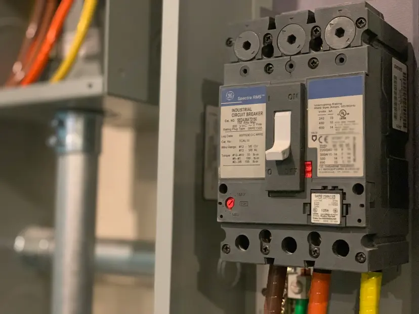
Circuit Breaker Coordination with LED Loads
Standard circuit breakers must be derated when controlling LED loads with conventional switching devices. The coordination depends on three key parameters:
- Circuit breaker rating (10A, 16A, 20A, etc.)
- Trip curve (B, C, or D curve)
- Control device technology (standard CT/TL vs. controlled iCT+/iTL+)
Breaker Curve Impact
Curve B: Most sensitive, trips at 3-5× rated current (typically 15-30 luminaires maximum)
Curve C: Medium sensitivity, trips at 5-10× rated current (standard for most installations)
Curve D: Least sensitive, trips at 10-20× rated current (handles larger inrush but offers less short-circuit protection)
Residential LED Circuit Example
Let's calculate a typical residential lighting circuit:
Scenario: Home office with 8 recessed LED downlights
Given:
- Luminaire power: 10W each
- Total connected load: 8 × 10W = 80W
- Supply voltage: 230V
- Circuit breaker: 10A, Curve C
- Standard contactor (CT)
Steady-state current:
From coordination tables (standard CT):
- 10A Curve C breaker with 10W LED luminaires: Maximum 15 fixtures
Our installation: 8 fixtures ✓ (within limit)
With controlled contactor (iCT+):
- Same breaker can handle 48 fixtures
- Circuit rated power:
The controlled contactor closes when voltage passes through zero, dramatically reducing the inrush surge. For this residential application, either approach works, but the iCT+ provides a 3× margin.
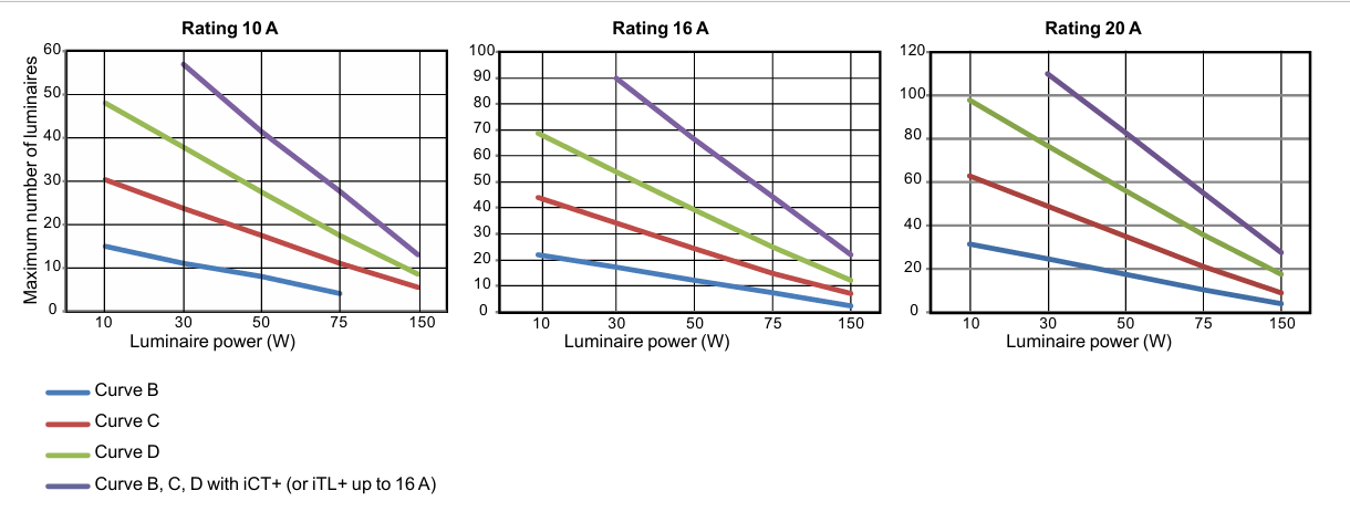
Photo by Schneider electric: Coordination of switchgear with loads
Figure: Coordination curves showing maximum LED luminaires vs. breaker rating for different control technologies.
Industrial LED Installation Calculation
Scenario: Factory floor LED high-bay lighting
Given:
- Luminaire power: 150W each
- Required luminaires: 25 fixtures
- Supply voltage: 230V
- Existing breaker: 20A, Curve C
Total connected load:
Steady-state current:
Check coordination table (20A Curve C, 150W LED):
- Standard contactor: 4 luminaires maximum
- Controlled contactor (iCT+): 28 luminaires maximum
Our requirement: 25 fixtures
Solution
- Standard switching: Would require 7 separate circuits (4 fixtures per circuit, with one circuit serving a single fixture)
- Using an iCT+ controlled contactor: A single 20A circuit can handle all 25 fixtures
Cost Analysis
-
7 standard circuits:
- 7× breakers
- 7× contactors
- Additional conduit, wiring, panel space, and labor
-
1 controlled circuit:
- 1× breaker
- 1× iCT+ contactor
-
Typical iCT+ premium:
- Approximately $50–80 over a standard contactor
-
Estimated project savings:
- Roughly $800–1,200 in materials and labor, depending on wiring distance and panel layout
This is one of the clearest examples of why controlled contactors make sense in larger LED installations. Once inrush current is considered, the reduction in breakers, wiring, and installation complexity can easily outweigh the higher device cost.
Technologies to Reduce Inrush Current
Soft-Start Function
Some LED drivers include integrated soft-start circuitry that gradually charges input capacitors. This extends the inrush period from milliseconds to 50-100ms, reducing peak current by 60-80%.
Controlled Contactors (iCT+, iTL+)
These devices close contacts when AC voltage crosses zero, minimizing the voltage differential that drives inrush current. Derating related to lamp technology becomes unnecessary.
Circuit rated power formula:
Dimmer Integration
Dimmer switches with soft-ramp capabilities can eliminate inrush entirely by gradually increasing voltage from zero to full.
Practical Sizing Tables
20A Circuit Breaker - LED Luminaires
| Luminaire Power | Curve B | Curve C | Curve D | With iCT+ |
|---|---|---|---|---|
| 10W | 32 | 63 | 98 | All |
| 30W | 25 | 49 | 77 | 110 |
| 50W | 18 | 35 | 56 | 83 |
| 75W | 11 | 21 | 36 | 55 |
| 150W | 4 | 9 | 18 | 28 |
16A Circuit Breaker - LED Luminaires
| Luminaire Power | Curve B | Curve C | Curve D | With iCT+ |
|---|---|---|---|---|
| 10W | 22 | 44 | 69 | All |
| 30W | 17 | 34 | 54 | 90 |
| 50W | 12 | 25 | 39 | 66 |
| 75W | 7 | 15 | 25 | 44 |
| 150W | 2 | 7 | 12 | 22 |
10A Circuit Breaker - LED Luminaires
| Luminaire Power | Curve B | Curve C | Curve D | With iCT+ |
|---|---|---|---|---|
| 10W | 15 | 30 | 48 | All |
| 30W | 11 | 24 | 38 | 57 |
| 50W | 8 | 17 | 27 | 41 |
| 75W | 4 | 11 | 17 | 28 |
| 150W | - | 5 | 9 | 13 |
Note: "All" indicates the breaker's thermal limit becomes the constraint, not inrush current.
Common Installation Mistakes
Mistake #1: Sizing Only for Continuous Load
In retrofit work, it’s common to see designs that look correct on paper: total wattage is calculated, the NEC 125% safety factor is applied, and breakers are selected accordingly—yet circuits still trip on first energization.
The issue usually isn’t the steady-state load—it’s LED inrush current.
Unlike incandescent or fluorescent loads, LED drivers behave like small switch-mode power supplies. On power-up, their internal capacitors charge almost instantly, creating a short but high current spike. This inrush current isn’t reflected in standard load calculations, but it can still dominate breaker behavior during startup.
In practice, LED inrush isn’t a “design detail”—it’s often the deciding factor in whether a properly sized circuit holds or nuisance-trips during commissioning.
Mistake #2: Mixing LED and Traditional Lighting
Combining LED fixtures with incandescent or fluorescent loads on the same circuit seems efficient but creates coordination nightmares. The combined inrush characteristics become unpredictable.
Mistake #3: Ignoring Control Device Selection
A standard contactor versus an iCT+ seems like an easy cost-cutting decision until you're running three additional circuits to make it work. Always model the complete system cost.
Mistake #4: Not Accounting for Future Expansion
That 12-fixture circuit at 75% capacity looks great today. Add four more fixtures next year and suddenly you're tripping breakers. With LEDs, design for the inrush, not just the load.
Key Takeaways for LED Circuit Design
When designing LED lighting circuits, remember:
- Inrush current is the design constraint, not steady-state load
- Breaker curve selection matters - Curve C is standard, but Curve D may be necessary for large installations
- Controlled contactors pay for themselves in installations above 2kW
- Reference manufacturer data - coordination tables are based on typical drivers; high-quality drivers may perform better
- Test during commissioning - verify inrush behavior under full-load switching conditions
LED technology transformed lighting efficiency but introduced new electrical challenges. Understanding inrush current and proper coordination between loads and protection devices isn't optional knowledge anymore—it's fundamental to reliable electrical design.
The coordination tables and calculations provided here come from field-tested installations and manufacturer data. When in doubt, measure actual inrush current with a power analyzer during a test installation. That will save you from costly circuit redesigns.
For more guidance on circuit protection and load calculations, see our complete circuit breaker sizing guide and motor cable sizing charts.
🔗 Related Posts
- UPS Sizing Guide: Complete Calculation with Battery Runtime & Load Analysis
- Power Factor Correction: Complete Guide with Calculators, Cost Analysis & Real Savings
- Voltage Drop Calculation: Ultimate Guide with NEC Tables & Free Calculator
- Wire Size Calculator: Complete Guide with Single Phase, 3-Phase & DC Calculations
Helpful Calculators
Credits
- Photo by Justin Lane on Unsplash
⭐ Was this article helpful?
IDAR Mohamed
Electrical Engineer
Electrical Engineer specialized in power systems, electrical installations, and energy efficiency. Passionate about simplifying complex electrical concepts into practical guides. (University of applied sciences graduate, with experience in HV/LV systems and industrial installations.)
- Circuit Protection
- Electrical Safety
- LED Technology
- Load Calculations