

Modbus Protocol: Complete Guide to RTU, TCP & ASCII with Wiring Examples
- Admin: IDAR Mohamed
- 21 Apr 2026
- 0
I've had quite a journey with Modbus in the world of industrial automation. It truly is the backbone of connectivity for millions of devices in factories, buildings, and energy facilities. In my experience, mastering Modbus—particularly RTU and TCP—has been essential for success.
I remember tackling a tricky network issue that had me stumped. It was through understanding the differences between Modbus RTU and TCP that I found solutions. Prioritizing the right protocol during my configurations made a remarkable difference. In sharing what I learned, I created a guide that focuses on the essential aspects of Modbus communication—from wiring tips to avoiding common mistakes. Hopefully, it can help others navigate challenges just as I did!
Table of Contents
- What is Modbus? Protocol Overview
- Modbus RTU: Serial Communication Protocol
- Modbus TCP/IP: Ethernet-Based Protocol
- Modbus RTU vs TCP: Complete Comparison
- Modbus Wiring and Network Design
- Register Mapping and Data Structures
- Troubleshooting and Best Practices
What is Modbus? Protocol Overview
History and Development
Modbus was developed by Modicon (now Schneider Electric) in 1979 as a simple, reliable communication protocol for industrial control systems. Its open specification and royalty-free use have made it the de facto standard for industrial automation.
Key Milestones:
- 1979: Original Modbus protocol released
- 1990s: Modbus Plus introduced for faster communication
- 1999: Modbus TCP specification published
- 2004: Modbus Organization formed, protocol becomes open standard
- Present: Over 7 million nodes installed worldwide
Modbus Architecture: Master-Slave Model
Modbus uses a master-slave (client-server) architecture where:
Master (Client):
- Initiates all communications
- Sends requests to slave devices
- Only one master per RTU network segment
- Can read/write data from multiple slaves
Slave (Server):
- Responds only when polled by master
- Cannot initiate communication
- Each slave has unique address (1-247)
- Processes requests and returns data
Modbus Protocol Variants
| Variant | Physical Layer | Encoding | Speed | Distance |
|---|---|---|---|---|
| Modbus RTU | RS-232, RS-485 | Binary | 9.6k-115k bps | 1,200m |
| Modbus ASCII | RS-232, RS-485 | ASCII text | 9.6k-19.2k bps | 1,200m |
| Modbus TCP | Ethernet | Binary (no CRC) | 10-1000 Mbps | 100m+ |
| Modbus Plus | Proprietary | Binary | 1 Mbps | 500m |
Why Modbus Remains Popular
Advantages:
- Simple and Reliable: Easy to implement and debug
- Open Standard: No licensing fees or proprietary restrictions
- Universal Support: Thousands of compatible devices available
- Interoperability: Devices from different manufacturers work together
- Mature Technology: Decades of proven performance
Limitations:
- No Built-in Security: No encryption or authentication (add VPN/firewall for TCP)
- Limited Bandwidth: RTU variants are relatively slow
- Polling Overhead: Master must poll each slave sequentially (RTU)
- Basic Data Types: Limited to 16-bit registers (requires combining for larger values)
Modbus RTU: Serial Communication Protocol
Modbus RTU Fundamentals
Modbus RTU (Remote Terminal Unit) is the most common Modbus variant, using serial communication over RS-485 or RS-232 physical layers with binary data encoding.
Key Characteristics:
- Binary Encoding: Compact, efficient data transmission
- RS-485 Multi-drop: Up to 32 devices on one network
- Master-Slave Only: Single master polls multiple slaves
- CRC Error Checking: 16-bit cyclic redundancy check for data integrity
Modbus RTU Frame Structure
Each Modbus RTU message consists of:
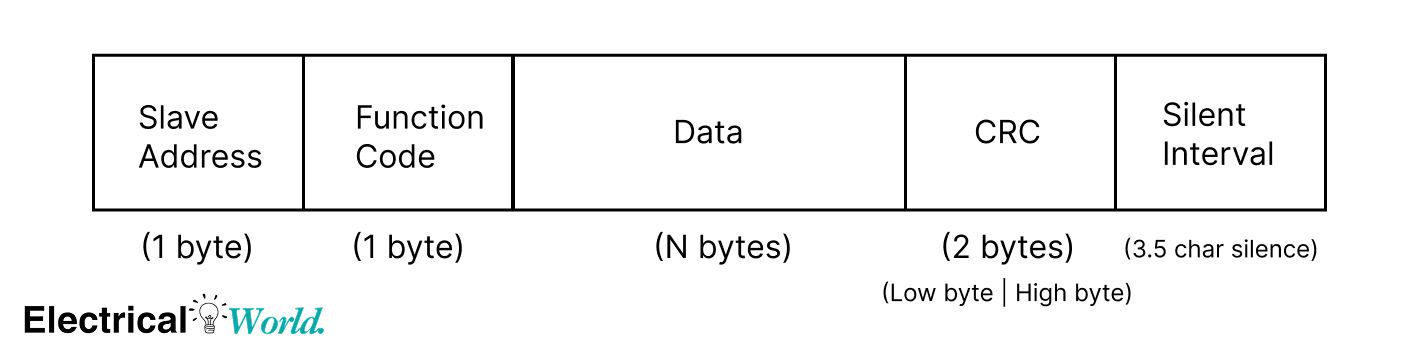
Frame Components:
| Field | Size | Description | Example |
|---|---|---|---|
| Slave Address | 1 byte | Device ID (1-247, 0=broadcast) | 01 = Device 1 |
| Function Code | 1 byte | Operation type | 03 = Read Holding Registers |
| Data | Variable | Request/response parameters | Address + quantity |
| CRC | 2 bytes | Error detection (Low byte, High byte) | Calculated checksum |
| Silent Interval | 3.5 char times | Frame delimiter | Marks message end |
Common Modbus Function Codes
| Code | Function | Description | Typical Use |
|---|---|---|---|
| 01 | Read Coils | Read 1-2000 discrete outputs | Digital outputs status |
| 02 | Read Discrete Inputs | Read 1-2000 discrete inputs | Switch/sensor states |
| 03 | Read Holding Registers | Read 1-125 16-bit registers | Process values, setpoints |
| 04 | Read Input Registers | Read 1-125 16-bit registers | Analog sensor readings |
| 05 | Write Single Coil | Write one discrete output | Turn relay ON/OFF |
| 06 | Write Single Register | Write one 16-bit register | Update setpoint |
| 15 | Write Multiple Coils | Write multiple discrete outputs | Control multiple outputs |
| 16 | Write Multiple Registers | Write multiple 16-bit registers | Bulk configuration |
Modbus RTU Communication Example
Read Temperature from Sensor (Device Address 1):
Master Request:
| Field | Value | Description |
|---|---|---|
| Slave Address | 01 | Device 1 |
| Function Code | 03 | Read Holding Registers |
| Start Address | 00 00 | Register 0 |
| Quantity | 00 01 | Read 1 register |
| CRC | 84 0A | Calculated checksum |
01 03 00 00 00 01 84 0A
Slave Response:
| Field | Value | Description |
|---|---|---|
| Slave Address | 01 | Device 1 |
| Function Code | 03 | Read response |
| Byte Count | 02 | 2 bytes of data |
| Register Value | 00 B4 | Temperature = 180 = 18.0°C |
| CRC | 9E 60 | Calculated checksum |
01 03 02 00 B4 9E 60
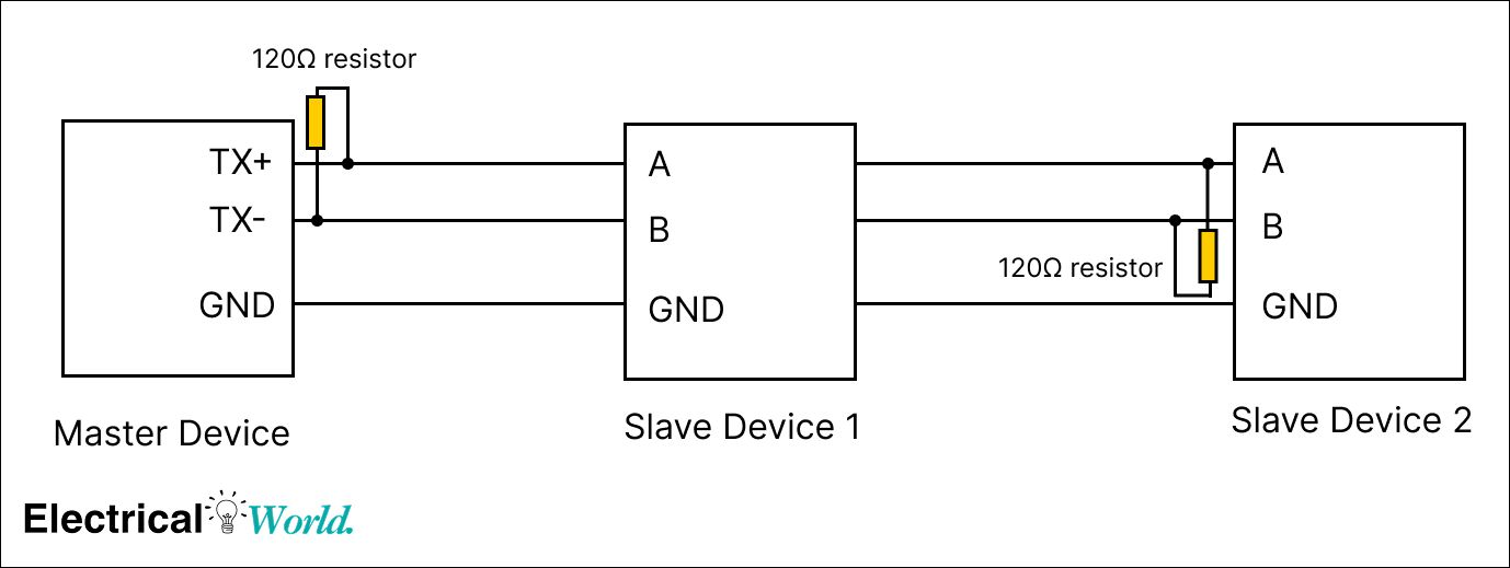
RS-485 Physical Layer for Modbus RTU
RS-485 Characteristics:
- Differential Signaling: Uses A (data+) and B (data-) lines
- Multi-drop Capable: Up to 32 devices without repeaters
- Noise Immunity: Excellent for industrial environments
- Two-Wire or Four-Wire: Half-duplex or full-duplex operation
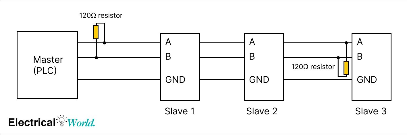
Standard RS-485 Wiring:
Modbus RTU Baud Rate Configuration
Common Baud Rates and Applications:
| Baud Rate | Max Distance | Use Case | Pros/Cons |
|---|---|---|---|
| 9600 bps | 1,200m (4,000 ft) | Long distances, noisy environments | Reliable, slower |
| 19200 bps | 1,000m (3,300 ft) | Standard industrial applications | Balanced speed/distance |
| 38400 bps | 500m (1,600 ft) | Shorter runs, higher throughput | Fast, more noise-sensitive |
| 57600 bps | 300m (1,000 ft) | Clean environments, short runs | Very fast, requires quality cable |
| 115200 bps | 100m (330 ft) | Local panel communications | Maximum speed, limited distance |
Configuration Parameters:
- Data Bits: 8 (standard for RTU)
- Parity: None, Even, or Odd
- Stop Bits: 1 or 2
- Example: 9600-N-8-1 (9600 baud, No parity, 8 data bits, 1 stop bit)
info
💡 Configuration Tip: All devices on a Modbus RTU network must use identical communication settings (baud rate, parity, stop bits). Even one mismatch will prevent communication.
Modbus RTU Network Topology
Daisy Chain Configuration:
Star/Spur Configuration (NOT Recommended):
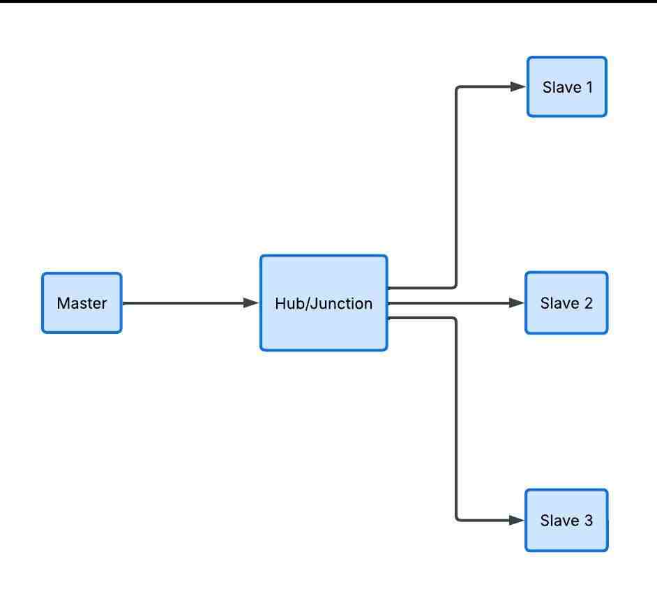
warning
⚠️ Topology Warning: Star/spur topologies create signal reflections and timing issues. Always use daisy-chain (linear bus) topology for Modbus RTU networks. Keep stubs under 1 meter if unavoidable.
Modbus TCP/IP: Ethernet-Based Protocol
Modbus TCP Fundamentals
Modbus TCP encapsulates Modbus messages within TCP/IP packets, enabling communication over standard Ethernet networks. It's essentially "Modbus RTU without the serial interface and CRC."
Key Characteristics:
- Ethernet Physical Layer: Uses standard Cat5e/Cat6 cabling
- TCP/IP Protocol Stack: Reliable, connection-oriented transmission
- Port 502: Default Modbus TCP port
- Multiple Masters: Multiple clients can connect simultaneously
- No Address Limits: Unlimited devices via IP addressing
Modbus TCP Frame Structure
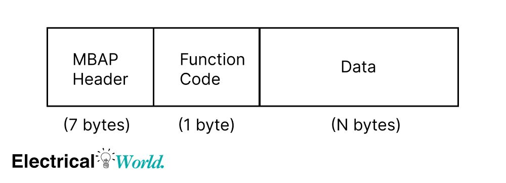
MBAP Header (Modbus Application Protocol):
| Field | Size | Description | Example |
|---|---|---|---|
| Transaction ID | 2 bytes | Message identifier | 00 01 |
| Protocol ID | 2 bytes | Always 00 00 for Modbus | 00 00 |
| Length | 2 bytes | Bytes following this field | 00 06 |
| Unit ID | 1 byte | Slave address (1-247) | 01 |
| Function Code | 1 byte | Operation type | 03 |
| Data | Variable | Request/response data | Varies |
Key Differences from RTU:
- No CRC: TCP provides error checking at transport layer
- MBAP Header: Replaces address/CRC with TCP information
- No Silent Interval: Frame timing handled by TCP
Modbus TCP Communication Example
Read Temperature from Device at IP 192.168.1.100:
Client Request (Modbus TCP)
- MBAP Header
| Field | Value | Description |
|---|---|---|
| Transaction ID | 00 01 | Message identifier |
| Protocol ID | 00 00 | Modbus protocol |
| Length | 00 06 | Bytes that follow |
| Unit ID | 01 | Device address |
- Modbus PDU
| Field | Value | Description |
|---|---|---|
| Function Code | 03 | Read Holding Registers |
| Start Address | 00 00 | Register 0 |
| Quantity | 00 01 | Read 1 register |
- Full TCP Frame
00 01 00 00 00 06 01 03 00 00 00 01
Server Response (Modbus TCP)
- MBAP Header
| Field | Value | Description |
|---|---|---|
| Transaction ID | 00 01 | Same request ID |
| Protocol ID | 00 00 | Modbus protocol |
| Length | 00 05 | Bytes that follow |
| Unit ID | 01 | Device address |
- Modbus PDU
| Field | Value | Description |
|---|---|---|
| Function Code | 03 | Read response |
| Byte Count | 02 | Number of bytes |
| Register Value | 00 B4 | 180 → 18.0°C |
- Full TCP Frame
00 01 00 00 00 05 01 03 02 00 B4
Modbus TCP Network Architecture
Typical Industrial Ethernet Setup:
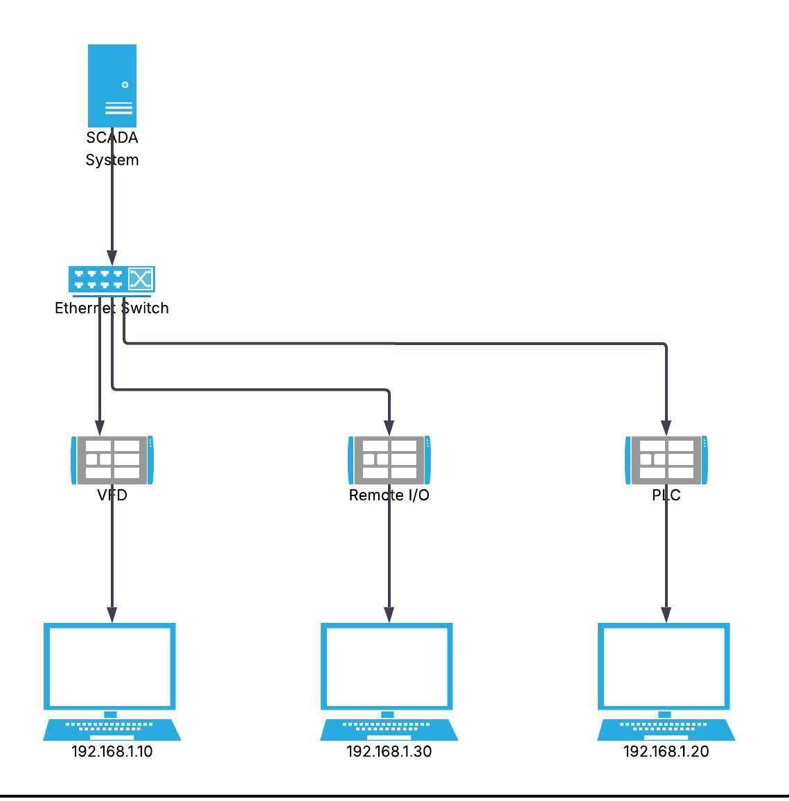
IP Address Planning:
| Device Type | IP Range | Example |
|---|---|---|
| SCADA/HMI | .1 - .10 | 192.168.1.5 |
| PLCs | .11 - .50 | 192.168.1.20 |
| VFDs/Drives | .51 - .100 | 192.168.1.60 |
| Remote I/O | .101 - .150 | 192.168.1.110 |
| Sensors/Meters | .151 - .200 | 192.168.1.175 |
Modbus TCP Advantages Over RTU
Performance Benefits:
| Aspect | Modbus TCP | Modbus RTU |
|---|---|---|
| Speed | 100 Mbps - 1 Gbps | 9.6k - 115k bps |
| Distance | 100m per segment, unlimited with switches | 1,200m maximum |
| Devices | Unlimited (IP-based) | 32 per segment |
| Simultaneous Access | Multiple clients | Single master only |
| Infrastructure | Standard Ethernet | Dedicated serial |
| Diagnostics | Network tools (Wireshark, ping) | Limited serial tools |
Integration Benefits:
- IT Infrastructure: Uses existing corporate networks
- Remote Access: Easy VPN and internet connectivity
- Network Management: SNMP monitoring and managed switches
- Scalability: Add devices without addressing limits
Modbus RTU vs TCP: Complete Comparison
Decision Matrix: When to Use Each Protocol
| Factor | Use Modbus RTU When: | Use Modbus TCP When: |
|---|---|---|
| Cost | Budget-conscious, simple installations | Infrastructure already available |
| Distance | Short to medium (< 1km) | Long distances via switches/fiber |
| Speed | Low data rates acceptable | High-speed data transfer needed |
| Device Count | < 32 devices per segment | Large networks (100+ devices) |
| Existing Infrastructure | Legacy serial devices | Ethernet network in place |
| IT Integration | Standalone system | SCADA/MES/ERP integration |
| Maintenance | Limited IT support | Network monitoring available |
| Security Requirements | Physical security sufficient | Cybersecurity critical |
Performance Comparison
Response Time Analysis:
Modbus RTU (9600 baud)
- Single register read: ~20–60 ms
- 10 register read: ~50–150 ms
- Polling 10 devices (1 reg each): ~200–600 ms (sequential polling)
Modbus TCP (100 Mbps)
- Single register read: ~5–20 ms
- 10 register read: ~10–40 ms
- Polling 10 devices (1 reg each): ~50–200 ms (can be parallel depending on master)
Note: Actual performance depends on PLC scan time, device processing delay, network load, and request/response optimization.
Key Differences:
- RTU: Sequential → latency adds up per device
- TCP: Can be parallel → faster system-level response
- Both: Faster when reading multiple registers in one request
Protocol Overhead Comparison
Reading 1 Register:
Modbus RTU Frame:
Total: 8 bytes
├─ Address:     1 byte
├─ Function:    1 byte
├─ Start Addr:  2 bytes
├─ Quantity:    2 bytes
└─ CRC:         2 bytes
Modbus TCP Frame:
Total: 12 bytes + TCP/IP overhead (~40 bytes)
├─ MBAP Header: 7 bytes
│  ├─ Trans ID:    2 bytes
│  ├─ Protocol:    2 bytes
│  ├─ Length:      2 bytes
│  └─ Unit ID:     1 byte
├─ Function:    1 byte
├─ Start Addr:  2 bytes
└─ Quantity:    2 bytes
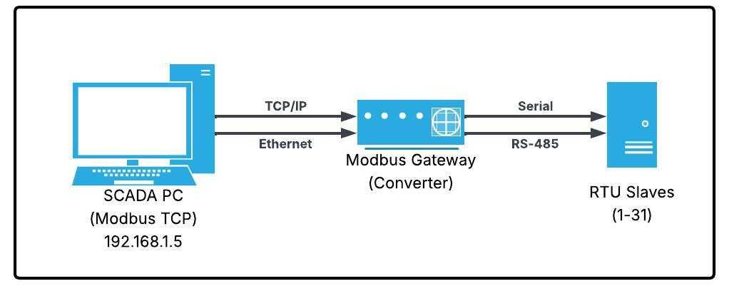
Modbus RTU to TCP Conversion
Gateway/Converter Requirements:
Modbus gateways bridge RTU and TCP networks by:
- Protocol Translation: Converts RTU frames to TCP packets
- Address Mapping: Maps RTU slave addresses to TCP Unit IDs
- Timing Adaptation: Handles different response times
- Buffering: Queues requests between protocols
Common Gateway Types:
| Gateway Type | Description | Use Case |
|---|---|---|
| Hardware Gateway | Standalone converter box | Industrial environments, multiple RTU devices |
| Software Gateway | PC-based conversion | SCADA integration, testing |
| PLC Gateway | Built into PLC firmware | Allen-Bradley, Siemens systems |
| Embedded Module | Modbus-enabled device | VFDs, meters with dual protocol |
Gateway Wiring Example:
Cost Analysis: RTU vs TCP
Cost Comparison: Modbus RTU vs Modbus TCP (10 Devices)
Modbus RTU (RS-485)
- RS-485 converter/gateway: $50–150
- Cabling (500 m, shielded twisted pair): $100–300
- Device interface cost: $0–50 per device (if not built-in)
Total: ~$200–600
Modbus TCP (Ethernet)
- Ethernet switch (unmanaged): $50–200
- Cabling (500 m, Cat5e/Cat6): $80–250
- Device Ethernet cost: $0–150 per device (or external gateways)
Total: ~$200–1200
Note: Actual costs vary depending on whether communication interfaces are built into devices or require add-on modules.
Quick Take
- Modbus RTU: Lower cost, simpler hardware, but more wiring constraints
- Modbus TCP: Higher cost, easier scaling, better integration with modern systems (SCADA, cloud)
info
💡 Cost Consideration: While TCP infrastructure costs more initially, it offers better scalability and integration. For new installations with >20 devices or IT network requirements, TCP often proves more cost-effective long-term.
Modbus Wiring and Network Design
Modbus RTU Wiring Best Practices
RS-485 Two-Wire Half-Duplex Wiring
Standard Configuration:
Wiring Color Codes:
| Signal | Standard Color | Alternative | Purpose |
|---|---|---|---|
| A (Data+) | Green or Yellow | Red | Positive differential |
| B (Data-) | Blue or White | Black | Negative differential |
| GND/Common | Black or Bare | Shield | Signal reference |
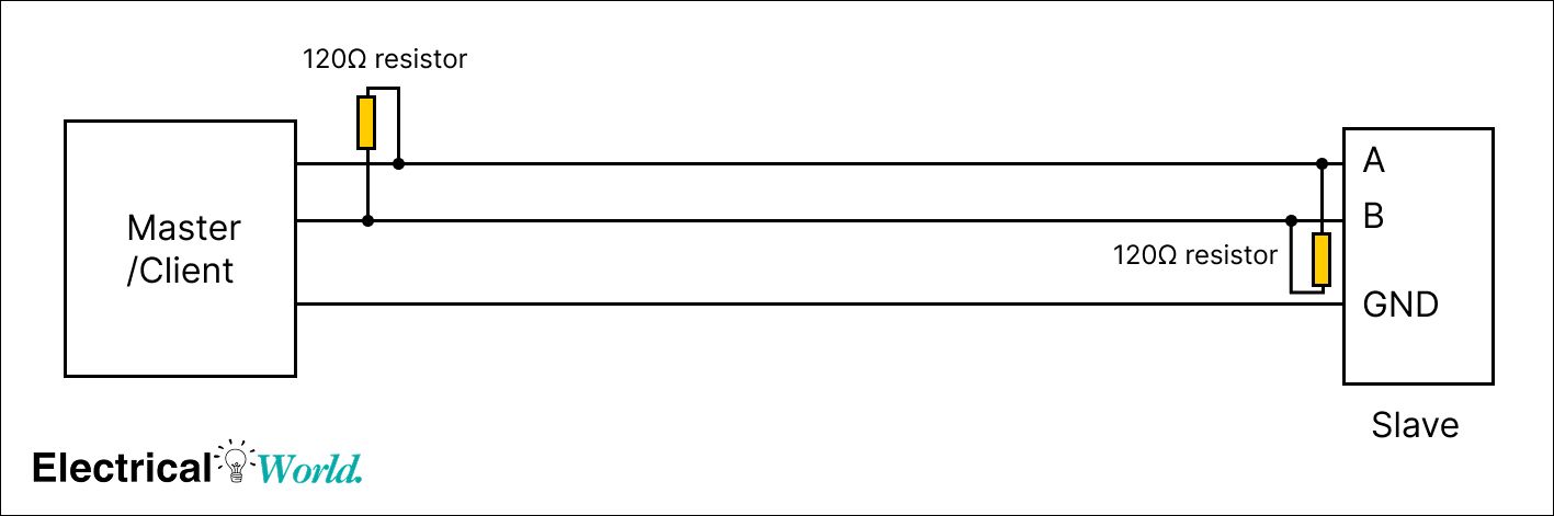
Termination Resistors
Why Termination is Critical:
- Signal Reflection: Without termination, signals bounce back causing errors
- Voltage Stability: Maintains proper signal levels
- Noise Immunity: Reduces susceptibility to interference
Termination Requirements:
- Value: 120Ω ± 5% (matches cable impedance)
- Location: Both ends of the bus (first and last device)
- Type: 1/4W resistor minimum, or built-in termination
Cable Selection for Modbus RTU
Recommended Cable Specifications:
| Parameter | Specification | Why It Matters |
|---|---|---|
| Type | Shielded twisted pair | Noise rejection |
| Impedance | 120Ω characteristic | Match termination |
| Gauge | 18-24 AWG | Balance distance/cost |
| Capacitance | < 100 pF/m | Signal integrity |
| Pairs | 1 pair minimum | Data transmission |
| Shield | Foil or braid | EMI protection |
Shield Grounding (RS-485 / Modbus):
- Ground the shield at one end only → prevents ground loops
- Prefer grounding at the master side → better noise drainage
- Leave the other end floating (not connected)
- Use the drain wire to connect the shield to earth ground
Modbus TCP Network Design
Switch Selection
Required Switch Features:
| Feature | Requirement | Benefit |
|---|---|---|
| Port Speed | 100 Mbps minimum | Adequate bandwidth |
| Port Count | Plan for 30% growth | Future expansion |
| Management | Optional for < 20 devices | Network diagnostics |
| QoS | Recommended for critical data | Priority traffic |
| IGMP Snooping | For multicast applications | Efficient bandwidth use |
Managed vs Unmanaged:
- Unmanaged: Plug-and-play, low cost, simple networks
- Managed: VLAN support, port mirroring, diagnostics, larger networks
Ethernet Cabling Standards
Cable Categories:
| Category | Bandwidth | Max Distance | Modbus Use |
|---|---|---|---|
| Cat5e | 1 Gbps | 100m | Standard choice |
| Cat6 | 10 Gbps | 55m | Future-proof |
| Cat6a | 10 Gbps | 100m | Industrial/long runs |
| Fiber Optic | 10+ Gbps | 2km+ | Long distances |
Connector Types:
- RJ45: Standard Ethernet connector
- M12: Industrial-rated, vibration-resistant
- Fiber (SC/LC): Long-distance, electrical isolation
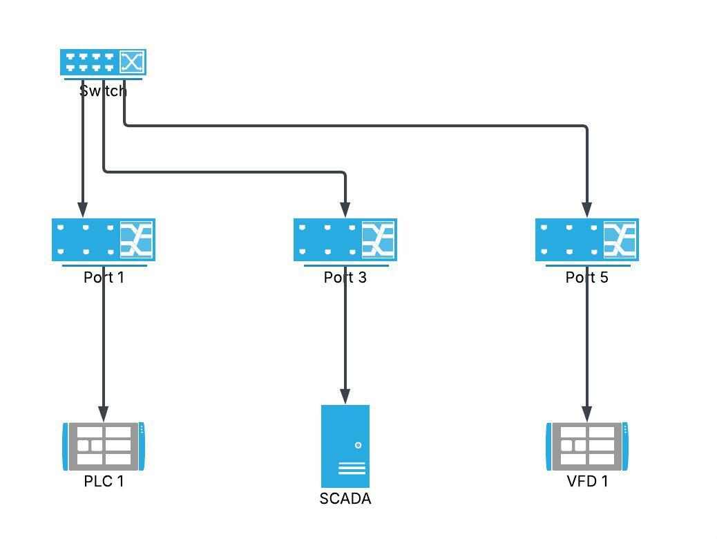
Network Topology Considerations
Star Topology (Recommended for TCP):
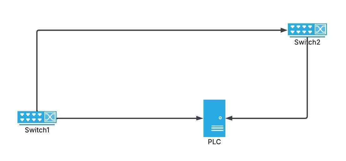
Ring Topology (Redundancy):
Grounding and EMI Protection
Grounding Best Practices:
- Single Point Ground: Avoid ground loops
- Low Impedance Path: Use heavy gauge wire (#12 AWG or larger)
- Earth Ground: Connect to building earth ground system
- Equipment Bonding: Connect all device chassis together
EMI Mitigation Techniques:
- Separate Power/Signal: Minimum 12" (30 cm) spacing
- Conduit Use: Metal conduit provides shielding
- Surge Protection: Install at both ends of long runs
- Filtering: Use ferrite cores on cables near noise sources
Register Mapping and Data Structures
Modbus Address Spaces
Modbus defines four primary data tables:
| Data Type | Access | Address Range | Size | Use Case |
|---|---|---|---|---|
| Coils | Read/Write | 00001-09999 | 1 bit | Digital outputs (relays) |
| Discrete Inputs | Read Only | 10001-19999 | 1 bit | Digital inputs (switches) |
| Holding Registers | Read/Write | 40001-49999 | 16 bit | Configuration, setpoints |
| Input Registers | Read Only | 30001-39999 | 16 bit | Analog readings, status |
Address Notation Confusion:
Protocol (Zero-Based):
Holding Register 0 = Address 0x0000
Modicon (One-Based):
Holding Register 40001 = Address 0x0000
warning
⚠️ Address Warning: Always verify whether your device uses zero-based or one-based addressing. This is the #1 cause of "device not responding" errors. Check the device manual for register mapping conventions.
Common Data Type Encoding
16-bit Integer (INT16):
- Range: -32,768 to +32,767
- Registers: 1
- Example: Temperature reading = 250 (25.0°C with 0.1 scaling)
32-bit Integer (INT32):
- Range: -2,147,483,648 to +2,147,483,647
- Registers: 2 (consecutive)
- Byte Order: Big-endian or little-endian (check device)
32-bit Float (IEEE 754):
- Range: ±3.4 × 10³⁸
- Registers: 2 (consecutive)
- Example: 3.14159 stored across two registers
Byte Order (Endianness):
| Format | Description | Register Order |
|---|---|---|
| Big-endian (AB CD) | Most significant first | Reg0: AB, Reg1: CD |
| Little-endian (DC BA) | Least significant first | Reg0: CD, Reg1: AB |
| Big-endian swap (BA DC) | Word-swapped | Reg0: BA, Reg1: DC |
| Little-endian swap (CD AB) | Byte/word-swapped | Reg0: DC, Reg1: BA |
Example Register Map
VFD (Variable Frequency Drive) Register Map:
| Register | Function | Type | Units | R/W |
|---|---|---|---|---|
| 40001 | Motor Speed | INT16 | RPM | R |
| 40002 | Output Frequency | INT16 | 0.1 Hz | R |
| 40003 | Output Current | INT16 | 0.1 A | R |
| 40004 | DC Bus Voltage | INT16 | V | R |
| 40010 | Speed Setpoint | INT16 | RPM | R/W |
| 40011 | Accel Time | INT16 | 0.1 s | R/W |
| 40012 | Decel Time | INT16 | 0.1 s | R/W |
| 40100 | Run Command | BOOL | - | W |
| 40101 | Stop Command | BOOL | - | W |
Reading Motor Speed (Function Code 03):
Request:
  Device: 01
  Function: 03 (Read Holding Registers)
  Address: 0000 (Register 40001)
  Quantity: 0001 (1 register)

Response:
  Device: 01
  Function: 03
  Byte Count: 02
  Data: 05 DC (1500 RPM)
Troubleshooting and Best Practices
Common Modbus Communication Errors
Error Codes and Meanings
| Error Code | Name | Cause | Solution |
|---|---|---|---|
| 01 | Illegal Function | Unsupported function code | Check device capabilities |
| 02 | Illegal Data Address | Register doesn't exist | Verify address map |
| 03 | Illegal Data Value | Invalid data range | Check value limits |
| 04 | Slave Device Failure | Device error condition | Check device status |
| 05 | Acknowledge | Long operation in progress | Wait and retry |
| 06 | Slave Device Busy | Device processing | Implement retry logic |
Modbus RTU Troubleshooting
No Response from Slave:
Check List:
- ✓ Power: Verify slave device has power
- ✓ Wiring: A connected to A, B to B
- ✓ Address: Correct slave address configured
- ✓ Baud Rate: All devices match (9600, 19200, etc.)
- ✓ Parity: All devices use same setting
- ✓ Termination: 120Ω resistors at both ends
- ✓ Cable Length: Within 1200m limit
Diagnostic Tools:
- Multimeter: Check voltage on A/B lines (should see ~0-5V differential)
- Modbus Scanner: Software to scan for devices
- Serial Analyzer: Capture and decode frames
- Oscilloscope: View signal quality (advanced)
Modbus TCP Troubleshooting
Connection Failures:
Check List:
- ✓ IP Address: Correct device IP and subnet
- ✓ Port: Using port 502 (default)
- ✓ Network Cable: Link lights on both ends
- ✓ Firewall: Port 502 allowed through
- ✓ Switch Config: VLANs not blocking traffic
- ✓ Ping Test: Device responds to ping
- ✓ Unit ID: Correct Unit ID in MBAP header
Network Diagnostic Commands:
# Test connectivity
ping 192.168.1.100

# Check if port 502 is open
telnet 192.168.1.100 502

# Trace network route
tracert 192.168.1.100

# View ARP table
arp -a
Wireshark Packet Analysis:
- Filter: modbus or tcp.port == 502
- Look for: Transaction IDs matching request/response
- Check: Unit ID and function codes
- Verify: Response times (should be < 100ms typically)
Performance Optimization
Modbus RTU Optimization:
| Technique | Improvement | Implementation |
|---|---|---|
| Increase Baud Rate | 2-4x faster | Use 38400 or 57600 if cable allows |
| Reduce Polling | Lower bus load | Poll critical data more frequently |
| Block Reads | Fewer transactions | Read 10 registers vs 10 single reads |
| Optimize Timeout | Faster recovery | Set based on baud rate (50-500ms) |
Modbus TCP Optimization:
| Technique | Improvement | Implementation |
|---|---|---|
| Persistent Connections | Eliminate handshake | Keep TCP connection open |
| Parallel Queries | Simultaneous reads | Multiple client threads |
| QoS Configuration | Prioritize traffic | Configure switch for Modbus priority |
| Reduce Distance | Lower latency | Minimize switch hops |
Security Best Practices
Modbus has NO built-in security. Implement defense-in-depth:
Network Segmentation:
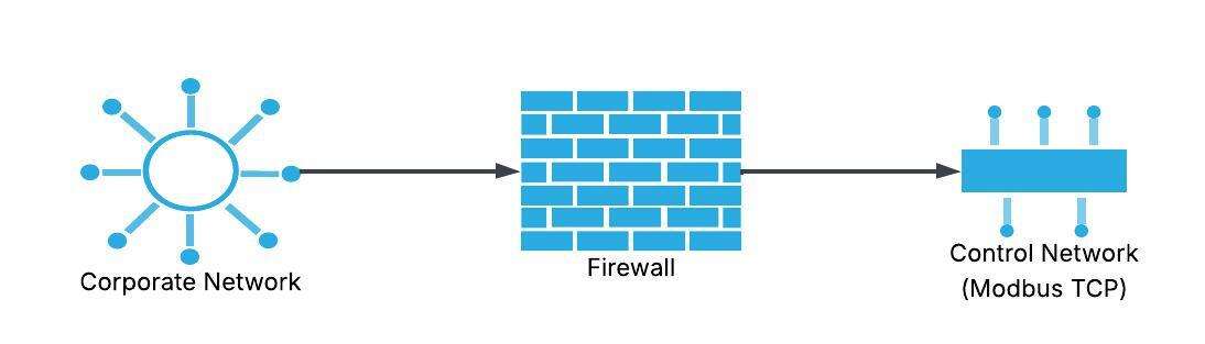
Security Measures:
| Layer | Protection | Implementation |
|---|---|---|
| Physical | Access control | Locked cabinets, restricted areas |
| Network | Firewall | Allow only port 502, specific IPs |
| Application | Authentication | VPN for remote access |
| Monitoring | IDS/IPS | Detect abnormal Modbus traffic |
Recommendations:
- Isolate OT networks: Separate from corporate IT
- Use VPN: For any remote Modbus TCP access
- Monitor traffic: Log all Modbus transactions
- Disable unused ports: On switches and devices
- Update firmware: Patch known vulnerabilities
Real-World Applications and Examples
PLC to VFD Communication
Application: SCADA controlling 5 VFDs via Modbus RTU
Network Configuration:
┌──────────┐
│   PLC    │ RS-485 Master
│ (Master) │ Baud: 9600, N, 8, 1
└────┬─────┘
     │ 120Ω termination
     │
     ├─────┐ VFD 1 (Address 1)
     │
     ├─────┐ VFD 2 (Address 2)
     │
     ├─────┐ VFD 3 (Address 3)
     │
     ├─────┐ VFD 4 (Address 4)
     │
     └─────┐ VFD 5 (Address 5)
           120Ω termination
PLC Ladder Logic Example:
Scan cycle every 100ms:
1. Read VFD 1 speed (FC03, register 40001)
2. Read VFD 1 current (FC03, register 40003)
3. Write VFD 1 setpoint (FC06, register 40010)
4. Repeat for VFDs 2-5
Total scan time: ~500ms
Energy Monitoring System
Application: Building management system reading 20 power meters
Network: Modbus TCP over Ethernet
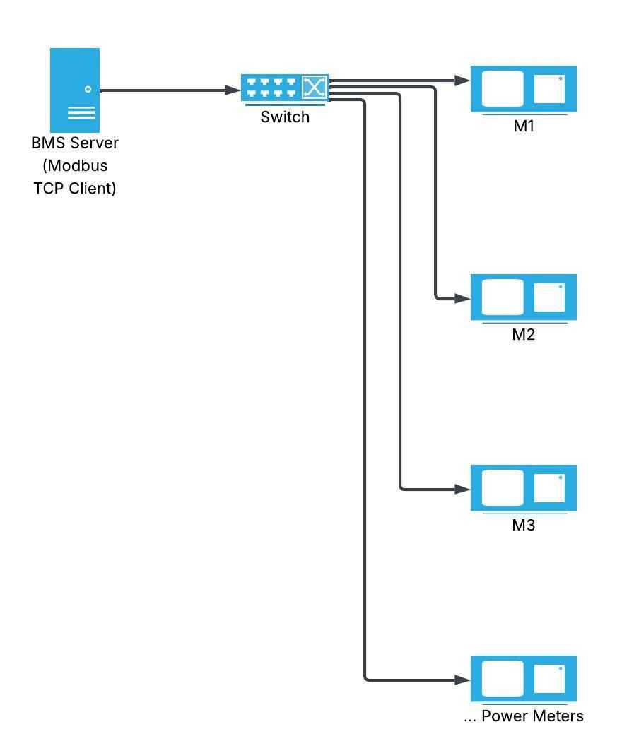
Data Collection:
- Frequency: Every 15 seconds
- Parameters per meter: Voltage, current, power, energy
- Registers read: 10 per meter
- Total transaction rate: 20 meters × 4 parameters = 80 reads/15s
- Network load: Negligible on 100 Mbps Ethernet
SCADA Integration
Application: Water treatment plant with mixed protocols
Gateway Solution:
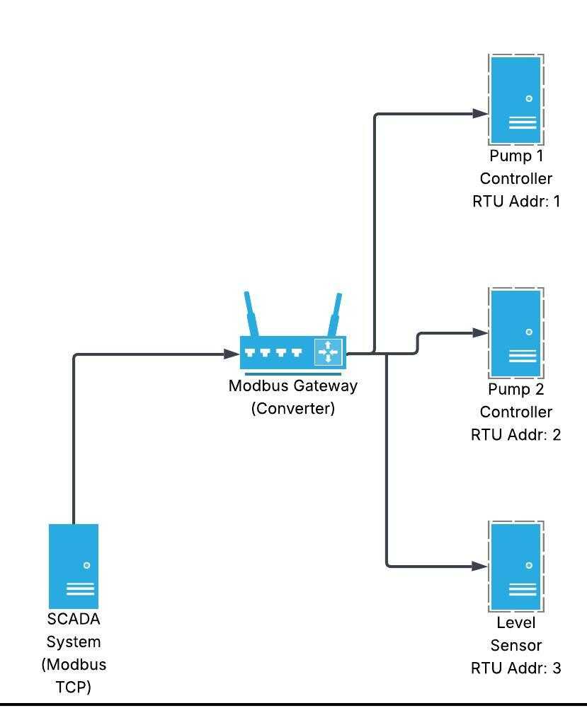
Register Mapping:
- SCADA sees all devices as TCP Unit IDs
- Gateway translates to RTU addresses
- Single IP for entire RTU network
- Simplified SCADA configuration
Conclusion: Choosing the Right Modbus Protocol
Modbus remains the universal language of industrial automation, with Modbus RTU and TCP serving different but complementary roles. Understanding when to use each protocol, how to implement them correctly, and how to troubleshoot common issues is essential for reliable industrial communication systems.
Key Decision Factors:
Choose Modbus RTU when:
- Budget is constrained
- Simple point-to-point or small networks (< 32 devices)
- Legacy equipment integration required
- Standalone systems without IT infrastructure
- Electrically noisy environments (excellent noise immunity)
Choose Modbus TCP when:
- Ethernet infrastructure exists
- Large device count (> 32)
- High-speed data transfer needed
- IT network integration required (SCADA, MES, ERP)
- Remote monitoring/diagnostics important
- Cybersecurity measures can be implemented
Best Practices Summary:
- Plan Your Network: Document addresses, register maps, and topology
- Follow Wiring Standards: Proper termination and shielding prevent 90% of issues
- Configure Correctly: Match all communication parameters across devices
- Test Systematically: Use diagnostic tools to verify connectivity
- Monitor Performance: Track response times and error rates
- Implement Security: Protect Modbus TCP networks with firewalls and VPNs
- Document Everything: Maintain network diagrams and device configurations
Whether you're modernizing a legacy system with Modbus RTU or building a new facility with Modbus TCP, understanding these protocols ensures reliable, maintainable industrial communication networks. For advanced applications, consider hybrid approaches using gateways to leverage the strengths of both protocols.
Ready to implement Modbus in your facility? Start with our related guides on PLC programming, Smart grids and energy, and industrial automation and VFD best practices.
🔗 Related Posts
- PLC Programming Basics: Complete Beginner's Guide
- Variable Frequency Drive (VFD): The Complete Guide
- I2C vs SPI: Complete Comparison Guide
- Short Circuit & Fault Current Calculation
- Star Delta Starter: Complete Wiring Guide
Helpful Calculators
- Ohm's Law Calculator
- Voltage Drop Calculator
- Power Factor Calculator
- Capacitor and Inductor Reactance Calculator
Credits
- Photo by Homa Appliances on Unsplash
⭐ Was this article helpful?
IDAR Mohamed
Electrical Engineer
Electrical Engineer specialized in power systems, electrical installations, and energy efficiency. Passionate about simplifying complex electrical concepts into practical guides. (University of applied sciences graduate, with experience in HV/LV systems and industrial installations.)
- Modbus RTU
- Modbus TCP
- Industrial Communication