
PLC Programming Basics: Complete Beginner's Guide (Step-by-Step with Examples)
- Admin: IDAR Mohamed
- 20 Sep 2025
- 0
If you've ever wondered how modern factories operate with such precision and efficiency, the answer lies in PLC programming. Programmable Logic Controllers (PLCs) are the invisible workhorses behind nearly every automated manufacturing process, from automotive assembly lines to food packaging systems.
Whether you're an electrical engineering student, a maintenance technician looking to advance your career, or simply curious about industrial automation, this comprehensive guide will take you from complete beginner to confident PLC programmer. We'll cover everything from basic concepts to hands-on programming examples, ensuring you have the practical knowledge needed to start your automation journey.
By the end of this guide, you'll understand how PLCs work, master the fundamentals of ladder logic programming, and be able to create your own control programs for real-world applications.
Table of Contents
- What is a PLC? Understanding the Foundation of Industrial Automation
- Why PLCs are Essential for Modern Automation
- Main Components of a PLC System: Building Blocks of Automation
- PLC Programming Languages: Choosing the Right Tool
- Step-by-Step PLC Program Example: Motor Control with Start/Stop
- Troubleshooting Your PLC Program
- Common Mistakes Beginners Make (And How to Avoid Them)
- Conclusion: Master the Fundamentals, Build Your Expertise
What is a PLC? Understanding the Foundation of Industrial Automation
A Programmable Logic Controller (PLC) is a specialized industrial computer designed to control manufacturing processes, machinery, and other automated systems in real-time. Think of it as the "brain" that makes decisions based on input conditions and controls outputs accordingly.
How PLCs Revolutionized Industrial Control
Before PLCs were invented in 1968 by Dick Morley, industrial control systems relied on complex networks of mechanical relays, timers, and switches. These relay-based systems had significant limitations:
- Difficult to modify: Changing control logic required rewiring
- Hard to troubleshoot: Finding faults in relay circuits was time-consuming
- Space-intensive: Large control panels filled with hundreds of relays
- Maintenance-heavy: Mechanical components wore out frequently
PLCs solved these problems by replacing physical relays with software-based logic that could be easily modified, monitored, and maintained.
Real-World PLC Applications
PLCs are everywhere in modern industry:
| Industry | Common Applications | Typical Functions |
|---|---|---|
| Manufacturing | Assembly lines, robotic cells | Sequence control, safety interlocks |
| Automotive | Paint booths, welding stations | Process timing, quality control |
| Food & Beverage | Bottling lines, packaging | Recipe management, sanitation cycles |
| Water Treatment | Pump stations, filtration | Level control, chemical dosing |
| Building Automation | HVAC systems, lighting | Energy management, scheduling |
| Oil & Gas | Pipeline control, refineries | Safety systems, process optimization |
Why PLCs are Essential for Modern Automation
Understanding the advantages of PLCs will help you appreciate why they've become the standard for industrial control:
1. Reliability and Durability
PLCs are designed for harsh industrial environments:
- Operating temperatures from -40°C to +70°C
- Resistance to vibration, dust, and electromagnetic interference
- Mean Time Between Failures (MTBF) often exceeding 100,000 hours
- No moving parts in solid-state designs
2. Flexibility and Programmability
Unlike hardwired control systems:
- Logic changes require only software modifications
- Multiple control strategies can be stored and selected
- Easy to add new features or expand system capabilities
- Standardized programming languages ensure portability
3. Cost-Effectiveness
While initial costs may be higher than relay systems:
- Reduced installation time and wiring costs
- Lower maintenance requirements
- Easier troubleshooting reduces downtime
- Energy efficiency through optimized control
4. Safety and Compliance
Modern PLCs include built-in safety features:
- Watchdog timers prevent runaway conditions
- Fail-safe outputs protect equipment and personnel
- Integrated safety functions meet international standards
- Diagnostic capabilities enable predictive maintenance
Main Components of a PLC System: Building Blocks of Automation
Understanding PLC hardware components is crucial for effective programming and troubleshooting. Let's explore each component in detail:
1. Central Processing Unit (CPU)
The CPU is the heart of the PLC system, responsible for:
Core Functions:
- Program execution: Processes the user program in a continuous scan cycle
- Memory management: Stores program logic, data, and system parameters
- Communication: Manages data exchange with I/O modules and networks
- Diagnostics: Monitors system health and reports faults
Key Specifications:
- Processing speed: Measured in microseconds per instruction
- Memory capacity: Program memory (KB-MB) and data memory
- I/O capacity: Maximum number of input/output points supported
- Communication ports: Ethernet, serial, fieldbus interfaces
2. Input/Output (I/O) Modules
I/O modules interface the PLC with real-world devices:
Digital Input Modules
Convert field signals to digital logic levels:
- DC inputs: 12V, 24V DC for proximity sensors, push buttons
- AC inputs: 120V, 240V AC for limit switches, contactors
- Isolation: Optical isolation protects CPU from field voltage spikes
- Filtering: Debouncing circuits eliminate contact bounce
Digital Output Modules
Control discrete field devices:
- Relay outputs: Mechanical contacts for high-power switching
- Transistor outputs: Fast switching for DC loads
- Triac outputs: Solid-state switching for AC loads
- Current ratings: Typically 0.5A to 2A per output
Analog I/O Modules
Handle continuous signals:
- Analog inputs: 4-20mA, 0-10V for temperature, pressure sensors
- Analog outputs: Control valve positions, variable speed drives
- Resolution: 12-bit to 16-bit accuracy for precise control
- Scaling: Convert engineering units to digital values
3. Power Supply Unit
The power supply provides stable DC power for PLC operation:
Specifications:
- Input voltage: 85-264V AC or 24V DC
- Output voltage: Typically 5V, 24V DC
- Current capacity: Sized for CPU and I/O module requirements
- Efficiency: >85% for energy savings
- Protection: Over-voltage, over-current, and short-circuit protection
⚡ Working on similar calculations?
Get practical electrical tips and quick answers like this — straight to your inbox.
4. Programming Device
The programming device is your interface to the PLC:
Hardware Options:
- Laptop/PC: Most common, running PLC programming software
- Handheld programmer: Portable device for basic programming
- Built-in display: Some PLCs include integrated HMI screens
Software Features:
- Program editors: Ladder logic, function block, structured text
- Simulation: Test programs without physical hardware
- Online monitoring: View real-time I/O status and data values
- Documentation: Generate reports and backup programs
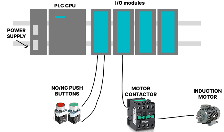
PLC System Architecture Example
Here's how these components work together in a typical motor control application:
PLC Programming Languages: Choosing the Right Tool
The IEC 61131-3 international standard defines five programming languages for PLCs. Understanding when and why to use each language is essential for effective automation programming.
1. Ladder Logic (LD) - The Industry Standard
Ladder Logic is the most widely used PLC programming language, representing about 80% of all PLC programs in industry.
Why Ladder Logic Dominates:
- Visual similarity: Resembles electrical relay circuit diagrams
- Intuitive understanding: Electricians can quickly grasp the concepts
- Universal support: Every PLC manufacturer supports ladder logic
- Troubleshooting: Easy to follow signal flow and identify problems
Key Elements of Ladder Logic:
Contacts (Inputs):
- Normally Open (NO):
] [- True when input is energized - Normally Closed (NC):
]/[- True when input is de-energized - Rising Edge:
]P[- True for one scan when input turns ON - Falling Edge:
]N[- True for one scan when input turns OFF
Coils (Outputs):
- Output coil:
( )- Energizes output when rung is true - Set coil:
(S)- Latches output ON until reset - Reset coil:
(R)- Turns output OFF - Negated coil:
(/)- Inverts the logic state
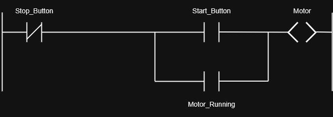
Basic Ladder Logic Example:
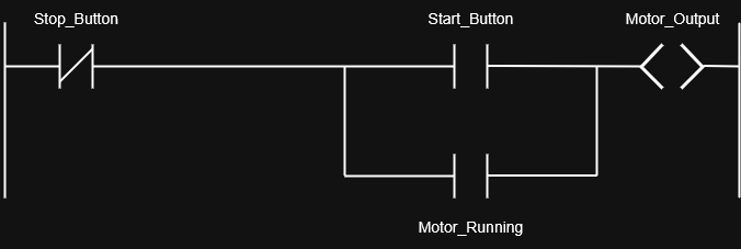
This rung implements a basic start/stop circuit with seal-in logic.
2. Function Block Diagram (FBD) - Modular Programming
Function Block Diagram uses graphical blocks to represent functions:
Advantages:
- Modular approach: Reusable function blocks
- Complex math: Ideal for calculations and data processing
- Signal flow: Clear representation of data movement
- Process control: Perfect for PID loops and analog control
Common Function Blocks:
- Math blocks: ADD, SUB, MUL, DIV for calculations
- Logic blocks: AND, OR, NOT for Boolean operations
- Timing blocks: TON, TOF, TP for time-based functions
- Control blocks: PID, RAMP, LIMIT for process control

3. Structured Text (ST) - Programming Power
Structured Text is a high-level programming language similar to Pascal:
When to Use ST:
- Complex algorithms: Mathematical calculations and data manipulation
- Conditional logic: Multiple nested IF-THEN-ELSE statements
- Loop operations: FOR, WHILE loops for repetitive tasks
- String handling: Text processing and communication protocols
Structured Text Example:
PROGRAM MotorControl
VAR
    StartButton   : BOOL;     (* Input - Start pushbutton *)
    StopButton    : BOOL;     (* Input - Stop pushbutton *)
    MotorRunning  : BOOL;     (* Internal latch bit *)
    MotorOutput   : BOOL;     (* Output to motor contactor *)
END_VAR

(* Latching logic *)
IF StartButton AND NOT StopButton THEN
    MotorRunning := TRUE;     (* Set latch *)
END_IF;

IF StopButton THEN
    MotorRunning := FALSE;    (* Reset latch *)
END_IF;

(* Output follows latch state *)
MotorOutput := MotorRunning;
4. Instruction List (IL) - Assembly-Style Programming
Instruction List uses mnemonic instructions similar to assembly language:
Characteristics:
- Compact code: Minimal memory usage
- Fast execution: Direct processor instructions
- Legacy systems: Found in older PLC programs
- Expert use: Requires deep understanding of PLC architecture
(* Motor Start/Stop in Instruction List *)

LD     StartButton     (* Load Start button *)
ANDN   StopButton      (* AND with NOT Stop button *)
OR     MotorRunning    (* OR with memory (latch) *)
ST     MotorRunning    (* Store back into latch *)

LD     MotorRunning    (* Load latch state *)
ST     MotorOutput     (* Drive motor output *)
5. Sequential Function Chart (SFC) - Process Flow Control
Sequential Function Chart defines sequential processes with steps and transitions:
Perfect for:
- Batch processes: Recipe-based manufacturing
- Machine sequences: Step-by-step operations
- Safety systems: Defined operational states
- Complex workflows: Multi-stage processes
SFC Elements:
- Steps: Represent process states or activities
- Transitions: Conditions that advance to the next step
- Actions: Operations performed in each step
- Branches: Parallel or alternative paths
(* Define steps *)
STEP Idle:
    IF StartButton THEN
        TRANSITION TO Starting;
    END_IF;

STEP Starting:
    MotorRunning := TRUE;
    TRANSITION TO Running;

STEP Running:
    MotorOutput := TRUE;
    IF StopButton THEN
        TRANSITION TO Stopping;
    END_IF;

STEP Stopping:
    MotorRunning := FALSE;
    MotorOutput := FALSE;
    TRANSITION TO Idle;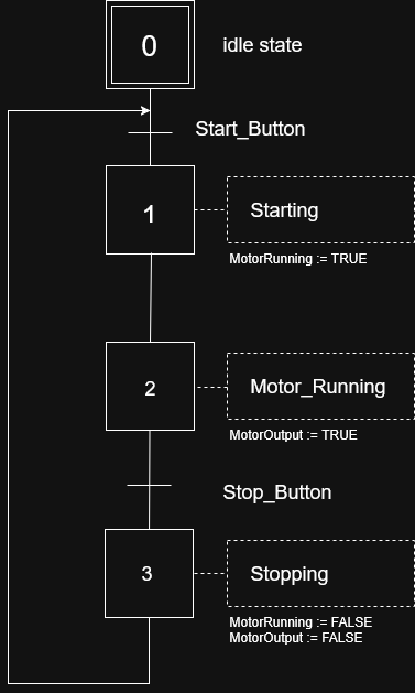
Step-by-Step PLC Program Example: Motor Control with Start/Stop
Let's create a practical PLC program that demonstrates fundamental concepts. This example will control a motor with start and stop buttons, including safety features and status indication.
Project Requirements
Objective: Control a conveyor motor with the following specifications:
Inputs:
- Start button (normally open pushbutton)
- Stop button (normally closed pushbutton)
- Emergency stop (normally closed mushroom button)
- Motor overload contact (normally closed)
Outputs:
- Motor contactor
- Green "Running" pilot light
- Red "Stopped" pilot light
Control Logic:
- Motor starts when start button is pressed
- Motor continues running until stop button is pressed
- Emergency stop immediately shuts down motor
- Motor overload trips shutdown motor and prevent restart
- Status lights indicate motor condition
Hardware Configuration
First, let's assign I/O addresses for our devices:
| Device | Type | Address | Description |
|---|---|---|---|
| Start Button | Digital Input | I0.0 | Momentary NO pushbutton |
| Stop Button | Digital Input | I0.1 | Momentary NC pushbutton |
| E-Stop | Digital Input | I0.2 | Emergency stop NC |
| Motor O/L | Digital Input | I0.3 | Overload contact NC |
| Motor Contactor | Digital Output | Q0.0 | Motor starter coil |
| Green Light | Digital Output | Q0.1 | Running indicator |
| Red Light | Digital Output | Q0.2 | Stopped indicator |
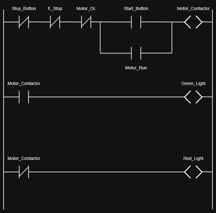
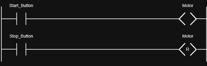
Ladder Logic Program Implementation
Rung 1: Main Motor Control Logic

Program Logic Explanation:
- Start condition: Start button (I0.0) must be pressed AND all safety inputs true
- Seal-in logic: Motor_Contactor output (Q0.0) seals itself in through contact
- Stop conditions: Any of the following will stop the motor:
- Stop button pressed (I0.1 goes FALSE)
- Emergency stop activated (I0.2 goes FALSE)
- Motor overload trips (I0.3 goes FALSE)
Rung 2: Green Running Light
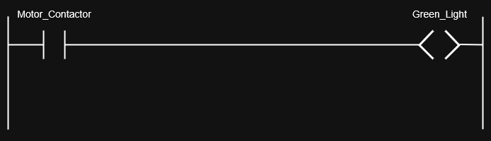
The green light is ON whenever the motor contactor is energized.
Rung 3: Red Stopped Light
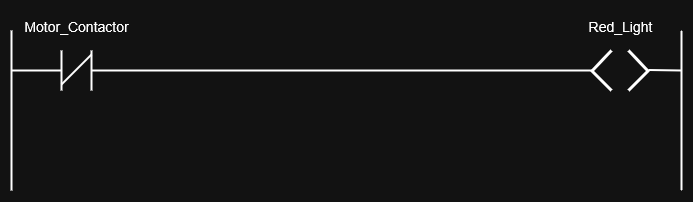
The red light is ON whenever the motor contactor is de-energized.
Complete Ladder Logic Program
Program Download and Testing
Step 1: Programming Software Setup
- Open PLC software (examples: RSLogix, TIA Portal, GX Works)
- Create new project and select your PLC model
- Configure I/O modules and assign addresses
- Enter ladder logic using the programming interface
Step 2: Program Verification
Before downloading to the PLC:
- Check syntax: Ensure no programming errors
- Simulate program: Test logic without physical I/O
- Verify addresses: Confirm I/O mapping is correct
- Add comments: Document program for future maintenance
Step 3: Download and Commission
- Connect to PLC via communication cable or network
- Download program to PLC memory
- Switch to RUN mode to execute the program
- Test operation: Verify each input/output function
Enhanced Features You Can Add
As you become more comfortable with PLC programming, consider adding these features:
Timer Functions
Add a start delay or minimum run time:
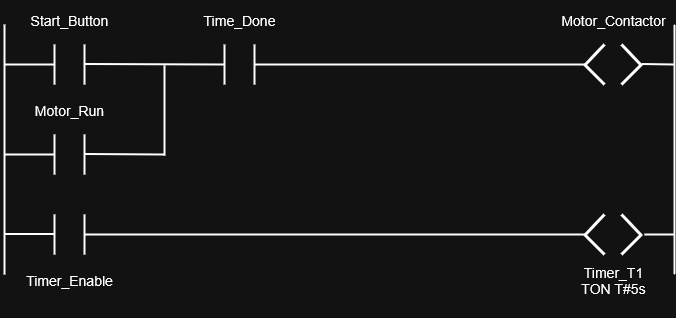
Counter Applications
Count motor starts for maintenance scheduling:

HMI Integration
Connect to Human Machine Interface for:
- Remote start/stop control
- Real-time status monitoring
- Alarm history and diagnostics
- Production data collection
Troubleshooting Your PLC Program
When your program doesn't work as expected:
Common Issues and Solutions:
-
Motor won't start:
- Check all input devices are properly wired and functioning
- Verify I/O addresses match physical connections
- Ensure PLC is in RUN mode
-
Motor won't stop:
- Check stop button wiring and operation
- Verify emergency stop circuit integrity
- Look for programming logic errors in stop conditions
-
Lights not working:
- Confirm output module has power supply
- Check output fuse/protection devices
- Verify correct output addresses in program
Diagnostic Tools:
- Online monitoring: Watch I/O status in real-time
- Force I/O: Manually control inputs/outputs for testing
- Cross-reference: Find all uses of each address
- Trend data: Monitor values over time
Common Mistakes Beginners Make (And How to Avoid Them)
Learning from common mistakes can accelerate your PLC programming journey. Here are the most frequent errors new programmers make:
1. Poor I/O Documentation and Organization
The Mistake:
- Using generic names like "Input1", "Output2"
- No comments explaining program logic
- Inconsistent addressing schemes
The Solution:
// Good Practice Example
I0.0    // Start_PB_Main_Motor      - Green start pushbutton
I0.1    // Stop_PB_Main_Motor       - Red stop pushbutton
I0.2    // E_Stop_Main_Panel        - Emergency stop mushroom
Q0.0    // Motor_Main_Contactor     - 480V motor starter
Best Practices:
- Use descriptive names that indicate function and location
- Create I/O lists and keep them updated
- Add comments for every rung explaining the logic
- Use consistent naming conventions throughout the project
2. Ignoring Scan Cycle and Timing Issues
The Mistake: Not understanding that PLCs execute programs sequentially in a scan cycle, leading to timing problems.
The Problem Example:
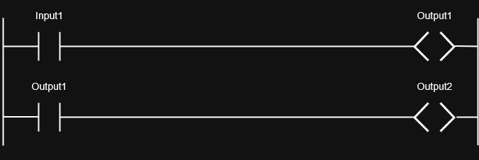
The Solution:
Understanding Scan Cycle:
- Input scan: Read all physical inputs
- Program execution: Process logic from top to bottom
- Output scan: Update all physical outputs
- Communication: Handle network traffic
- Repeat cycle: Typical scan time 1-10 milliseconds
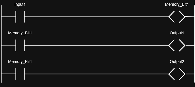
3. Improper Use of Latching Logic
The Mistake: Creating rungs that fight each other or don't properly maintain state.
Common Error:
Correct Implementation:
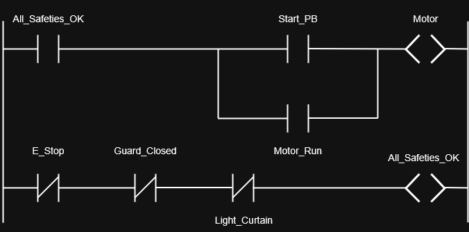
4. Neglecting Safety Considerations
The Mistake: Programming without considering fail-safe operation and emergency conditions.
Safety Programming Principles:
- Fail-safe design: System should fail to a safe state
- Redundant safety: Critical safety functions should have backup
- Emergency stop priority: E-stops must override all other logic
- Lockout/tagout: Support for maintenance procedures
Example Safe Motor Control:
5. Overcomplicating Simple Logic
The Mistake: Using complex programming structures when simple logic would work better.
Overcomplicated Example:
// Unnecessarily complex
IF (Input1 = TRUE) AND (Input2 = FALSE) THEN
    IF (Timer1.Done = TRUE) THEN
        Output1 := TRUE;
    END_IF;
END_IF;
Simplified Ladder Logic:
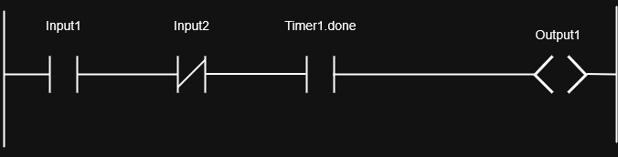
Simplification Guidelines:
- Use ladder logic for simple Boolean operations
- Reserve structured text for complex calculations
- Avoid nested IF statements when possible
- Keep logic intuitive for maintenance personnel
6. Inadequate Testing and Simulation
The Mistake: Downloading programs directly to equipment without proper testing.
Proper Testing Sequence:
- Desk check: Review logic manually for errors
- Simulation: Test program behavior using software simulator
- Bench test: Connect to actual I/O devices on workbench
- Staged commissioning: Test individual sections before full system
- Documentation: Record test results and any modifications
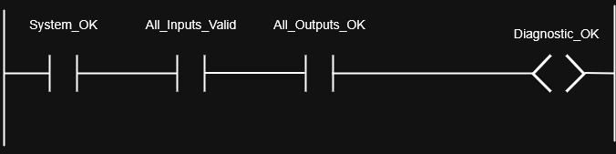
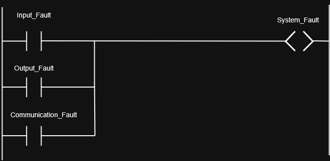
7. Poor Error Handling and Diagnostics
The Mistake: Not including diagnostic logic or error handling in programs.
Enhanced Program with Diagnostics:
8. Inconsistent Programming Standards
The Mistake: Each programmer using different styles and conventions.
Establish Standards:
- Naming conventions: Consistent prefixes and formats
- Program organization: Standard rung layout and grouping
- Documentation requirements: Mandatory comments and descriptions
- Code reuse: Standard function blocks and subroutines
Conclusion: Master the Fundamentals, Build Your Expertise
PLC programming is the foundation of modern industrial automation, and you now have the essential knowledge to begin creating control systems that power manufacturing around the world. From understanding basic ladder logic to implementing motor control circuits, these fundamentals will serve you throughout your automation career.
The key to mastering PLC programming is hands-on practice. Start with simple projects, experiment with programming software simulators, and gradually tackle more complex applications. Every program you write builds your expertise and opens new opportunities in the rapidly growing automation industry.
Ready to advance your automation skills? Explore our guides on Variable Frequency Drives and Motor Control Systems to deepen your industrial control knowledge.
🔗 Related Posts
- Complete Guide to Voltage Drop: Calculations, Tables & Calculators
- Power Factor Correction: Save Energy, Cut Costs & Improve Efficiency
- Kirchhoff's Laws: Complete Guide with Circuit Analysis Examples & Calculations
- Understanding AC Capacitors: Types, Functionality, and Applications
- Wire Size Calculator: Complete Guide with Single Phase, 3-Phase & DC Calculations
Helpful Calculators
- Voltage Drop Calculator
- Ohm's Law Calculator
- Power Factor Calculator
- Capacitor and Inductor Reactance Calculator
Credits
- Photo by Homa Appliances on Unsplash
⭐ Was this article helpful?
IDAR Mohamed
Electrical Engineer
Electrical Engineer specialized in power systems, electrical installations, and energy efficiency. Passionate about simplifying complex electrical concepts into practical guides. (University of applied sciences graduate, with experience in HV/LV systems and industrial installations.)
- PLC Programming
- Ladder Logic
- Industrial Automation
- Electrical Engineering
- Automation Programming
- PLC Basics
- SCADA Systems
- Industrial Controls