
AC Capacitors Explained: Types, Applications & Complete Sizing Guide with Calculations
- Admin: IDAR Mohamed
- 22 Oct 2024
- 0
AC capacitors are essential components in electrical and electronic systems, powering everything from residential air conditioning units to industrial motor control applications. Understanding how these capacitors work, how to select the right type, and how to properly size them for your application is crucial whether you're a homeowner troubleshooting HVAC problems, an electrician installing motor circuits, or an engineer designing power systems.
This comprehensive guide explains AC capacitor fundamentals, working principles, types, applications, sizing calculations, and practical troubleshooting techniques. You'll learn the differences between start and run capacitors, how to calculate reactive power compensation, and when to use power factor correction capacitors in industrial settings.
Understanding AC Capacitors: How They Work in Alternating Current Circuits
What is an AC Capacitor?
An AC capacitor is an electrical energy storage device designed specifically for alternating current (AC) circuits. Unlike DC capacitors that maintain a steady charge, AC capacitors continuously charge and discharge as the AC voltage alternates polarity, creating what's known as reactive power in the circuit.
The basic construction consists of two conductive metal plates separated by a dielectric insulating material. Common dielectric materials include polypropylene (for run capacitors), electrolytic compounds (for start capacitors), and paper-oil combinations (for power factor correction).
Working Principle of AC Capacitors
In AC circuits, capacitors exhibit unique behavior due to the constantly changing voltage:
Capacitive Reactance
The opposition a capacitor presents to AC current is called capacitive reactance (Xc), calculated as:
Where:
- = Capacitive reactance in ohms (Ω)
- = Frequency in hertz (Hz)
- = Capacitance in farads (F)
Phase Relationship in AC Circuits
In purely capacitive AC circuits, the current leads the voltage by 90 degrees. This phase shift is fundamental to how capacitors function in motor starting circuits and power factor correction applications.
The current through a capacitor is given by:
This relationship explains why current is maximum when voltage is changing most rapidly (at zero crossings) and zero when voltage reaches its peak.
Three Key Functions of AC Capacitors
AC capacitors serve three primary functions in electrical systems:
1. Reactive Power Compensation
Capacitors generate reactive power that opposes the inductive reactive power consumed by motors, transformers, and other inductive loads. This improves the overall power factor of the system, reducing wasted energy and utility penalties.
The reactive power supplied by a capacitor is:
Where:
- = Reactive power in volt-amperes reactive (VAR)
- = RMS voltage in volts
- = Frequency in hertz
- = Capacitance in farads
2. Voltage Stability and Regulation
By compensating reactive power locally, capacitors help maintain voltage levels throughout the distribution system. This reduces voltage drops during motor starting and improves overall system stability.
3. Phase Shift for Motor Starting
In single-phase motors, capacitors create the necessary phase difference between the main and auxiliary windings to produce the rotating magnetic field needed for starting and running the motor.
Types of AC Capacitors: Detailed Comparison and Applications
1. Run Capacitors
Run capacitors are designed for continuous operation in AC motor circuits and HVAC systems.
Construction and Characteristics
Dielectric Material: Metalized polypropylene film Operating Temperature: Typically -40°C to +85°C Duty Cycle: 100% continuous Tolerance: ±5% to ±10% Case Style: Oil-filled metal or plastic oval casing
Electrical Specifications
| Specification | Typical Range | Purpose |
|---|---|---|
| Capacitance | 5-50 μF | Continuous power factor correction |
| Voltage Rating | 370-440 VAC | Matches motor voltage plus safety margin |
| Insulation Class | Class B (130°C) or higher | Thermal protection |
| Dielectric Strength | >2000 VDC test | Prevents breakdown |
Applications
Run capacitors are found in:
- Central air conditioning compressor motors
- Heat pump fan motors
- Refrigeration equipment
- Ceiling fan motors
- Ventilation fans
- Pool pump motors
Example Calculation: Sizing a Run Capacitor for an AC Compressor
Given:
- Motor power: 3 HP (2,238 watts)
- Voltage: 240 VAC
- Frequency: 60 Hz
- Desired power factor improvement: 0.85 to 0.95
Step 1: Calculate motor current
Step 2: Calculate reactive power before correction
Step 3: Calculate reactive power after correction
Step 4: Required capacitor reactive power
Step 5: Calculate required capacitance
Result: Select a 30 μF, 370-440 VAC run capacitor
2. Start Capacitors
Start capacitors provide the high starting torque needed to overcome initial inertia in single-phase motors.
Construction and Characteristics
Dielectric Material: Electrolytic (aluminum oxide) Operating Temperature: -40°C to +70°C Duty Cycle: Intermittent (2-3 seconds per start) Tolerance: ±20% typical Case Style: Bakelite or plastic cylinder
Electrical Specifications
| Specification | Typical Range | Purpose |
|---|---|---|
| Capacitance | 50-300 μF | High starting torque |
| Voltage Rating | 110-330 VAC | Starting voltage surge handling |
| Maximum Operating Time | 3-5 seconds | Prevents overheating |
| Starting Torque Increase | 200-400% | Overcomes load inertia |
Start Capacitor Switching Mechanisms
Start capacitors disconnect after motor startup using:
- Centrifugal switch: Mechanical switch activated by motor speed
- Current relay: Electromagnetic relay sensing motor current drop
- PTC thermistor: Positive temperature coefficient device that increases resistance when hot
- Electronic relay: Solid-state timing circuit
Applications
Start capacitors are essential for:
- Air compressor motors
- Well pump motors
- Wood working machinery
- Large fan motors
- Conveyor systems
- Commercial refrigeration
Example: Calculating Start Capacitor Size
For a 1 HP, 120V, 60 Hz single-phase motor requiring high starting torque:
Rule of thumb: 50-100 μF per HP for start capacitors
Select: 88-108 μF, 110-125 VAC start capacitor (allowing for ±20% tolerance)
3. Power Factor Correction Capacitors
Industrial power factor correction capacitors improve efficiency in facilities with heavy inductive loads.
Construction and Characteristics
Dielectric Material: Metalized polypropylene or paper-oil Operating Temperature: -40°C to +55°C ambient Duty Cycle: Continuous Protection: Internal fusing, discharge resistors Configuration: Single-phase or three-phase banks
Sizing for Industrial Applications
Power factor correction capacitor sizing requires detailed load analysis:
Example: Factory Power Factor Correction
Given facility data:
- Total real power: 500 kW
- Current power factor: 0.75
- Target power factor: 0.95
- Voltage: 480V, 3-phase
- Frequency: 60 Hz
Step 1: Calculate current reactive power
Step 2: Calculate target reactive power
Step 3: Required capacitor bank size
Step 4: Capacitance per phase (delta connection)
Solution: Install a 280 kVAR three-phase capacitor bank with automatic switching
4. Dual Run Capacitors
Dual run capacitors combine two capacitors in one housing for space-saving HVAC applications.
Configuration
- One section for compressor motor (higher capacitance)
- One section for fan motor (lower capacitance)
- Three terminals: Common, HERM (compressor), FAN
Common Ratings
Typical dual run capacitor combinations:
- 35+5 μF, 370 VAC (3-ton AC unit)
- 40+5 μF, 440 VAC (4-ton AC unit)
- 45+7.5 μF, 370 VAC (5-ton AC unit)
- 50+10 μF, 440 VAC (large commercial units)
AC Capacitor Specifications: Understanding Key Parameters
Capacitance Rating (μF)
Capacitance measures the capacitor's ability to store electrical charge, expressed in microfarads (μF).
Tolerance Ranges:
- Run capacitors: ±5% to ±10%
- Start capacitors: ±20%
- Power factor correction: ±5%
Selection Criteria: Match manufacturer specifications within tolerance. Using higher capacitance than specified can damage motors or cause overheating.
Voltage Rating (VAC)
The voltage rating indicates the maximum RMS AC voltage the capacitor can safely withstand continuously.
Voltage Selection Guidelines
| System Voltage | Minimum Capacitor Rating | Recommended Rating |
|---|---|---|
| 120 VAC | 150 VAC | 165-250 VAC |
| 240 VAC | 300 VAC | 370-440 VAC |
| 277 VAC | 370 VAC | 440 VAC |
| 480 VAC | 550 VAC | 600-660 VAC |
Safety Factor: Always use capacitors rated at least 1.25× the system voltage for reliability and longevity.
Temperature Rating
Operating temperature significantly affects capacitor life and performance.
Temperature Effects on Capacitor Life
Temperature derating follows the Arrhenius equation:
Where:
- = Actual life
- = Rated life at reference temperature
- = Reference temperature (usually 85°C)
- = Operating temperature
Example: A capacitor rated for 60,000 hours at 85°C:
- At 75°C: 120,000 hours (2× life)
- At 95°C: 30,000 hours (0.5× life)
Insulation Class and Dielectric Strength
The insulation class defines the maximum safe operating temperature:
- Class A: 105°C
- Class B: 130°C
- Class F: 155°C
- Class H: 180°C
Dielectric strength (typically >2000 VDC test) ensures the capacitor withstands voltage spikes and transients without breakdown.
Motor Applications: Start and Run Capacitor Selection
Single-Phase Induction Motor Operation
Single-phase motors require capacitors to create a rotating magnetic field for starting and running.
Motor Types and Capacitor Requirements
| Motor Type | Capacitor Configuration | Starting Torque | Applications |
|---|---|---|---|
| Permanent Split Capacitor (PSC) | Run capacitor only | Medium (50-100% of rated) | Fans, blowers, pumps |
| Capacitor Start (CS) | Start capacitor only | High (200-350% of rated) | Air compressors, conveyors |
| Capacitor Start-Capacitor Run (CSCR) | Start + Run capacitors | Very high (300-450% of rated) | Heavy loads, difficult starts |
| Shaded Pole | No capacitor | Very low (30-50% of rated) | Small fans, toys |
Calculating Motor Capacitor Values
Run Capacitor Sizing Formula
For PSC motors, approximate run capacitor size:
Where:
- = Capacitance in microfarads
- = Motor power in watts
- = Constant (typically 2500-3500 for 60 Hz)
- = Voltage
Example: 1/2 HP (373W) motor at 240V
Select: 20 μF, 370 VAC run capacitor
Start Capacitor Sizing Formula
For CS motors, start capacitor approximation:
Example: 1 HP motor at 240V
But practical rule: 75-100 μF per HP gives 75-100 μF
Select: 88-108 μF, 250 VAC start capacitor
Motor Capacitor Wiring Diagrams
PSC Motor Wiring (Run Capacitor Only):
- Run capacitor connected between main and start windings
- Both windings remain energized during operation
- Most common in HVAC applications
CSCR Motor Wiring (Start + Run):
- Start capacitor in parallel with run capacitor during starting
- Start capacitor disconnected by centrifugal switch or relay
- Run capacitor remains in circuit during operation
- Provides highest starting torque
Power Factor Correction: Calculations and Benefits
Understanding Power Factor
Power factor (PF) is the ratio of real power (kW) to apparent power (kVA):
Where θ is the phase angle between voltage and current.
Power Triangle Relationships
The power triangle illustrates the relationship between:
- Real Power (P): Measured in kilowatts (kW)
- Reactive Power (Q): Measured in kilovolt-amperes reactive (kVAR)
- Apparent Power (S): Measured in kilovolt-amperes (kVA)
Benefits of Power Factor Correction
Improving power factor through capacitor installation provides:
1. Reduced Electrical Costs
- Lower utility demand charges (typically $5-15/kVA per month)
- Reduced energy consumption through lower line losses
- Avoidance of power factor penalties (below 0.90-0.95 PF)
2. Increased System Capacity
- Reduced current flow in conductors and equipment
- Ability to add loads without upgrading transformers
- Improved voltage regulation
3. Equipment Benefits
- Reduced heating in motors and transformers
- Lower voltage drop in distribution systems
- Extended equipment life
Power Factor Correction Calculations
Example: Industrial Facility Analysis
Current situation:
- Real power demand: 800 kW
- Power factor: 0.72 lagging
- Utility rate: $12/kVA demand charge
- Target power factor: 0.96
Step 1: Calculate current apparent power
Step 2: Calculate current reactive power
Step 3: Calculate target reactive power
Step 4: Required capacitor bank
Step 5: Calculate target apparent power
Step 6: Calculate monthly savings
Investment Analysis:
- Capacitor bank cost: ~$50,000 (530 kVAR installed)
- Monthly savings: $3,336
- Payback period: 15 months
- Annual ROI: 80%
Automatic Power Factor Correction
Modern facilities use automatic capacitor banks that switch stages on/off based on reactive power demand:
Controller Operation:
- Power factor relay monitors system PF continuously
- When PF drops below setpoint, contactors close to add capacitor stages
- When PF improves above setpoint, contactors open to remove stages
- Prevents over-correction and hunting
Typical Stage Sizes: 25, 50, 100, 200 kVAR per stage
HVAC System Capacitor Applications
Air Conditioning Capacitor Sizing
Central air conditioning systems typically require:
| AC Unit Size | Compressor Capacitor | Fan Motor Capacitor | Dual Run Option |
|---|---|---|---|
| 1.5 ton | 25-35 μF, 370V | 5 μF, 370V | 30+5 μF |
| 2 ton | 30-40 μF, 370V | 5 μF, 370V | 35+5 μF |
| 3 ton | 35-45 μF, 370V | 5-7.5 μF, 370V | 40+5 μF |
| 4 ton | 40-50 μF, 440V | 7.5 μF, 370V | 45+7.5 μF |
| 5 ton | 50-60 μF, 440V | 7.5-10 μF, 370V | 55+7.5 μF |
Important: Always verify capacitor values on the unit's wiring diagram. Ratings vary by manufacturer and model.
Heat Pump Capacitor Requirements
Heat pumps require capacitors for:
- Compressor motor (largest capacitance)
- Outdoor fan motor
- Indoor blower motor (some models)
- Reversing valve solenoid (small capacitance)
Refrigeration System Capacitors
Commercial refrigeration uses capacitors in:
- Walk-in cooler/freezer compressors
- Reach-in refrigerator compressors
- Display case evaporator fans
- Condenser fans
Special Considerations:
- Low ambient temperature operation
- Extended duty cycles (24/7 operation)
- Frequent start/stop cycles in defrost applications
Advanced Capacitor Topics
Capacitor Banks with Harmonic Filtering
Modern industrial facilities with variable frequency drives (VFDs) and electronic loads generate harmonics that can damage standard power factor correction capacitors.
Harmonic Resonance Issues
Capacitor banks can create resonance at harmonic frequencies:
Where:
- L = System inductance
- C = Capacitor bank capacitance
Solution: Install detuned (harmonic filter) capacitors with series reactors:
- 7% reactor for 3rd harmonic filtering
- 14% reactor for 5th harmonic filtering
Capacitor Switching Transients
Large capacitor banks create voltage transients when switched:
Inrush Current Calculation
For a 100 kVAR capacitor bank at 480V switched in 1 millisecond:
Mitigation Methods:
- Pre-insertion resistors
- Synchronous switching
- Series reactors
- Zero-crossing switches
Capacitor Life Expectancy and Reliability
Capacitor failure follows the bathtub curve:
Infant Mortality Period (0-1 year):
- Manufacturing defects
- Installation errors
- Incorrect sizing
Useful Life Period (1-15 years):
- Stable, predictable performance
- Random failures rare
Wear-Out Period (15+ years):
- Dielectric degradation
- Increased failure rate
- Preventive replacement recommended
Reliability Improvement Strategies:
- Select capacitors with conservative voltage ratings
- Install in climate-controlled environments
- Implement preventive maintenance program
- Monitor power factor and capacitor performance
- Replace at 80% of expected life
Capacitor Testing and Troubleshooting
Symptoms of Failing Capacitors
Visual Inspection Signs
- Bulging or swollen case
- Leaking oil or electrolyte
- Burn marks or discoloration
- Cracked or damaged terminals
- Corrosion on mounting bracket
Operational Symptoms
- Motor humming but not starting
- Hard starting (slow to come up to speed)
- Running backwards or at reduced speed
- Excessive heat generation
- Increased energy consumption
- Tripped breaker or blown fuse
Capacitor Testing Methods
Method 1: Analog Multimeter Test
- Discharge capacitor completely using insulated screwdriver across terminals
- Set multimeter to highest resistance (ohms) scale
- Connect meter leads to capacitor terminals
- Observe needle movement:
- Good capacitor: Needle swings toward zero then returns to infinity
- Shorted capacitor: Needle stays at zero
- Open capacitor: Needle doesn't move at all
Method 2: Digital Capacitance Meter
Most accurate testing method:
- Discharge capacitor completely
- Remove from circuit (at least one lead)
- Set meter to capacitance mode
- Connect meter leads to capacitor terminals
- Read capacitance value
- Compare to rated value:
- Good: Within ±10% of rating (run capacitors)
- Good: Within ±20% of rating (start capacitors)
- Failed: Below tolerance range
Method 3: In-Circuit Quick Test
For HVAC technicians in the field:
- Set multimeter to AC voltage
- Measure voltage across capacitor terminals with power on
- Turn off power and immediately measure voltage again
- Good capacitor: Retains voltage briefly after power off
- Bad capacitor: Voltage drops immediately to zero
Safety Warning: Always discharge capacitors before touching terminals, even after power is off.
Discharge Procedure for Capacitors
Critical Safety Step: Capacitors store dangerous voltage even when power is off.
Proper Discharge Method:
- Turn off all power to equipment
- Wait at least 5 minutes for internal discharge resistors
- Use 20,000-ohm, 2-watt resistor across terminals
- Hold resistor with insulated pliers
- Verify zero voltage with multimeter before touching
Never:
- Discharge with screwdriver (creates arc, damages terminals)
- Touch terminals before discharging
- Assume capacitor is safe because power is off
Capacitor Replacement and Installation Guidelines
Matching Replacement Capacitors
When replacing failed capacitors, match these specifications:
Critical Parameters (Must Match Exactly)
- Capacitance value (μF) - within tolerance
- Voltage rating (VAC) - equal or higher
- Type (run vs. start)
- Connection type (round vs. oval, terminal configuration)
Flexible Parameters
- Physical size - can be larger if space permits
- Brand - any quality manufacturer acceptable
- Case style - plastic or metal, round or oval
Installation Best Practices
Mounting Considerations:
- Install in cool location away from heat sources
- Vertical mounting preferred for oil-filled capacitors
- Secure mounting prevents vibration damage
- Allow air circulation around capacitor
Wiring Connections:
- Clean terminals before connecting
- Use properly sized terminals and connectors
- Secure wire connections to prevent loosening
- Route wires to prevent chafing or damage
Environmental Protection:
- Use weatherproof enclosures for outdoor installation
- Protect from moisture and condensation
- Consider vibration isolators for harsh environments
Practical Application Examples
Example 1: Sizing Capacitors for Window AC Unit
Given:
- Window AC unit: 12,000 BTU
- Compressor motor: 1/3 HP, 115V
- Fan motor: 1/12 HP, 115V
- Original capacitor failed (dual run type)
Solution:
Compressor capacitor sizing:
Fan capacitor sizing:
Replacement: 80+15 μF, 370 VAC dual run capacitor
Example 2: Industrial Motor Power Factor Correction
Given:
- 50 HP, 460V, 3-phase motor
- Operating power factor: 0.80
- Target power factor: 0.95
- Motor operates 16 hours/day, 250 days/year
Solution:
Motor power:
Current reactive power:
Target reactive power:
Required capacitor bank:
Installation: 15 kVAR three-phase capacitor bank at motor starter
Annual energy savings:
Payback period: 6-8 months
Example 3: Troubleshooting Non-Starting Pool Pump
Problem: 1 HP pool pump motor hums but won't start
Diagnosis Steps:
- Check power supply: Verified 240V at motor terminals ✓
- Check mechanical: Shaft rotates freely by hand ✓
- Test start capacitor: Measured 45 μF (rated 88-108 μF) ✗
Root Cause: Start capacitor degraded to 42% of rated value
Solution: Replace with 88-108 μF, 250 VAC start capacitor
Prevention: Start capacitors in hot pump house environment should be replaced every 3-5 years preventively
Capacitor Safety and Handling Procedures
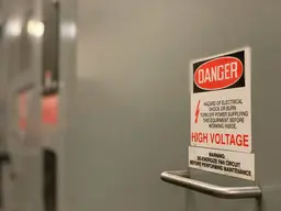
Electrical Hazards
AC capacitors present serious electrical hazards:
Stored Energy
Energy stored in a capacitor:
Example: 40 μF, 440V capacitor
While 3.87 joules may seem small, the rapid discharge can deliver dangerous current levels and cause severe burns or cardiac arrest.
Discharge Time Constants
Without discharge resistor, capacitors retain voltage for extended periods. The discharge time constant:
For a 40 μF capacitor with 10 MΩ internal resistance:
Time to discharge to 1% of initial voltage:
Safety Procedures
Before Working on Capacitors:
- Turn off all power sources
- Lock out/tag out electrical disconnect
- Wait minimum 5 minutes
- Discharge capacitor using proper resistor method
- Verify zero voltage with multimeter
- Keep discharge tool connected during work
Personal Protective Equipment:
- Insulated gloves rated for voltage
- Safety glasses
- Non-conductive footwear
- Insulated tools
Never:
- Work on energized capacitors
- Bypass discharge resistors
- Use metal objects to discharge
- Assume capacitor is discharged
Disposal and Environmental Considerations
PCB-Containing Capacitors
Older capacitors (pre-1979) may contain polychlorinated biphenyls (PCBs):
- Check for PCB warning labels
- Follow EPA regulations for disposal
- Use licensed hazardous waste disposal
Modern Capacitor Disposal
Most modern capacitors are non-hazardous but should be:
- Discharged completely before disposal
- Recycled when possible (metal case, aluminum foil)
- Disposed per local electronic waste regulations
Capacitor Selection Guide
Decision Matrix for Capacitor Selection
| Application | Capacitor Type | Key Specifications | Critical Factors |
|---|---|---|---|
| PSC Motor Run | Polypropylene run | 5-50 μF, 370-440V | Continuous duty, low losses |
| Motor Starting | Electrolytic start | 50-300 μF, 110-330V | High capacitance, short duty |
| Power Factor | Metalized film or oil-filled | Custom kVAR rating | Low losses, harmonic tolerance |
| HVAC Compressor | Oil-filled run | 20-60 μF, 370-440V | High temperature rating |
| Fan Motor | Dry film run | 2-15 μF, 370V | Compact size, reliable |
Quality and Brand Considerations
Premium Capacitor Brands
- Genteq/GE: Industry standard for HVAC
- Turbo: High-reliability run capacitors
- Mars: Wide range of motor capacitors
- Aerovox: Industrial power factor correction
- Ducati Energia: European power factor solutions
Quality Indicators
- UL listing or CSA approval
- Manufacturer warranty (3-5 years typical)
- Thick gauge terminals
- High-quality case construction
- Clear, permanent markings
⚙️ Budget vs. Premium Capacitors — Technical Comparison
The following figures are approximate industry ranges based on typical AC motor-run and power capacitors operating at 50/60 Hz, 230–480 V, and 40–60 °C ambient conditions.
| Aspect | Budget Capacitor | Premium Capacitor |
|---|---|---|
| Typical Price Range | ≈ 20 (USD) | ≈ 50 (USD) |
| Estimated Service Life | 3 – 8 years (≈ 5 000 – 20 000 h) | 10 – 15 years (≈ 30 000 – 60 000 h) |
| Approx. Annual Failure Rate | 8 – 15 % (after 5 years) | 1 – 3 % (after 10 years) |
| Typical Warranty | 1 year | 3 – 5 years |
| Total Cost of Ownership | Higher – due to earlier replacement and possible downtime | Lower – fewer replacements and better reliability |
Technical Notes
- Capacitor life expectancy roughly halves for every 10 °C increase in operating temperature (Arrhenius aging rule).
- Premium capacitors typically use metalized polypropylene or oil-filled designs rated for 10 000 – 30 000 hours at 70 °C.
- Budget capacitors often use thinner film or lower-grade electrolytes, typically rated for 3 000 – 10 000 hours.
- In HVAC and motor applications, ambient temperature, voltage stress, and ventilation are the main factors affecting service life.
⚠️ Actual performance can vary by manufacturer and operating environment. The above figures are technical estimates intended for comparison purposes only.
Recommendation: Use premium capacitors for critical applications and difficult-to-access installations.
Maintenance and Monitoring Programs
Preventive Maintenance Schedule
Monthly Tasks
- Visual inspection for physical damage
- Check for unusual sounds or vibration
- Monitor motor starting performance
- Verify proper ventilation
Quarterly Tasks
- Measure capacitance with meter
- Check mounting security
- Clean dust and debris
- Inspect electrical connections
Annual Tasks
- Full electrical testing
- Thermal imaging inspection
- Document capacitance values
- Replace capacitors approaching end of life
Predictive Maintenance Techniques
Infrared Thermography
Hot capacitors indicate:
- Internal dielectric breakdown
- High ESR (Equivalent Series Resistance)
- Overvoltage conditions
- Harmonic heating
Action Threshold: Replace if 20°F (11°C) above ambient or neighboring capacitors
Power Quality Analysis
Monitor for:
- Power factor trending downward
- Increasing reactive power demand
- Harmonic distortion levels
- Voltage imbalance
Capacitance Degradation Tracking
Create tracking database:
- Initial capacitance value
- Quarterly measurements
- Degradation rate calculation
- Predictive replacement date
Replacement Criterion: When capacitance drops below 85% of rated value
Cost-Benefit Analysis of Capacitor Applications
Run Capacitor Replacement Economics
Scenario: Commercial HVAC Unit with Failed Run Capacitor
Assume a 10-ton rooftop HVAC unit (≈10 kW motor load) operating 3,000 hours per year. Poor power factor due to a failed or weak run capacitor increases reactive current and energy losses.
| Option | Upfront Cost | Estimated Energy Cost / Year | Total 5-Year Cost (Energy + Replacement) |
|---|---|---|---|
| Continue Operation | $0 | ≈ $3,600 (due to low power factor) | ≈ $18,000 |
| Replace with Budget Capacitor | $40 | ≈ $2,800 | ≈ $14,040 |
| Replace with Premium Capacitor | $75 | ≈ $2,600 | ≈ $13,075 |
Analysis
- A failed run capacitor causes the motor to draw higher current, reducing efficiency and power factor.
- Premium capacitors maintain better capacitance stability over time, helping motors run cooler and more efficiently.
- Although the premium capacitor costs ~85% more upfront, it yields ≈$4,900 in total savings over 5 years, primarily through reduced energy loss and fewer replacements.
⚙️ Assumptions are based on a typical commercial HVAC load profile and electricity rate of $0.12–0.14/kWh. Actual savings vary with local tariffs, runtime, and system efficiency.
Power Factor Correction ROI Calculator
Input Parameters:
- Average demand: 1000 kW
- Current power factor: 0.75
- Target power factor: 0.95
- Utility demand charge: ≈ $15 / kVA
- Installed capacitor bank cost: ≈ $30 / kVAR
(Actual rates and costs vary by region, voltage level, and project scale.)
Calculations:
Current demand charge:
Improved demand charge:
Required capacitors:
Investment and returns:
Common Mistakes and How to Avoid Them
Mistake 1: Using Wrong Voltage Rating
Error: Installing 250V capacitor on 240V circuit Problem: Insufficient safety margin, premature failure Solution: Use minimum 370V rating for 240V circuits
Mistake 2: Swapping Start and Run Capacitors
Error: Installing start capacitor in run position Problem: Start capacitor overheats and fails quickly (not designed for continuous duty) Solution: Always verify capacitor type matches application
Mistake 3: Incorrect Dual Run Terminal Connection
Error: Connecting compressor to FAN terminal Problem: Wrong capacitance value, motor damage Solution:
- HERM terminal → Compressor (larger value)
- FAN terminal → Fan motor (smaller value)
- COMMON (C) → Shared connection
Mistake 4: Neglecting Voltage Transients
Error: Sizing capacitor exactly to system voltage Problem: Voltage spikes during switching cause failure Solution: Add 20-25% voltage safety margin
Mistake 5: Over-Correcting Power Factor
Error: Installing excessive capacitance to achieve unity power factor (1.0) Problem: Leading power factor, voltage rise, harmonic resonance Solution: Target 0.95-0.98 power factor, never exceed 0.99
Mistake 6: Ignoring Environmental Factors
Error: Using standard capacitor in hot attic installation Problem: Thermal degradation, shortened life Solution: Use high-temperature rated capacitors (105°C) or relocate
Future Trends in Capacitor Technology
Emerging Technologies
Film Capacitor Advancements
- Thinner dielectric films (higher capacitance density)
- Self-healing metallization layers
- Extended temperature ranges (-55°C to +125°C)
- Reduced size for same capacitance
Smart Capacitor Banks
- IoT-enabled monitoring
- Predictive failure analytics
- Automatic stage switching optimization
- Remote diagnostics and control
Dry-Type Capacitor Benefits
- No oil spills or environmental hazards
- Reduced maintenance requirements
- Lighter weight for easier installation
- Lower total cost of ownership
Integration with Renewable Energy
Capacitors play crucial roles in:
Solar PV Systems:
- Power factor correction for inverters
- Harmonic filtering
- Grid stabilization
Wind Power:
- Generator excitation
- Power quality improvement
- Voltage regulation
Energy Storage Integration:
- DC link capacitors in battery systems
- Active harmonic filtering
- Transient suppression
Conclusion: Selecting and Maintaining AC Capacitors for Optimal Performance
AC capacitors are fundamental components in modern electrical systems, from residential HVAC units to large industrial power factor correction installations. Understanding the differences between run and start capacitors, properly sizing capacitors for motor applications, and implementing power factor correction can significantly improve system efficiency, reduce operating costs, and extend equipment life.
Key takeaways for successful capacitor applications:
For Motor Applications:
- Match capacitor type (run vs. start) to motor design
- Size within manufacturer specifications
- Use proper voltage ratings with safety margin
- Replace at first signs of degradation
For Power Factor Correction:
- Calculate required kVAR accurately
- Consider harmonic environments
- Implement automatic switching for variable loads
- Monitor performance regularly
For Long-Term Reliability:
- Choose quality capacitors from reputable manufacturers
- Install in appropriate environmental conditions
- Follow preventive maintenance schedules
- Replace proactively based on age and measurements
Whether you're troubleshooting a non-starting air conditioner, designing a power factor correction system, or maintaining industrial equipment, the principles and calculations provided in this guide will help you select, size, and maintain AC capacitors for reliable, efficient operation.
For additional resources on electrical system design and maintenance, explore our guides on motor control, power distribution, and electrical safety practices.
🔗 Related Posts
- Understanding Induction Motors: Working Principle, Calculations, and Applications
- Power Factor Correction: Complete Guide with Calculators, Cost Analysis & Real Savings
- Variable Frequency Drive (VFD): The Complete Guide to Working Principles, Types, and Applications
- Complete Guide to Voltage Drop: Calculations, Tables & Calculators
- Understanding Electric Current: A Comprehensive Guide
- Circuit Breaker Sizing: Complete Guide with Wire Size Charts & NEC Code Requirements
Helpful Calculators
Credits
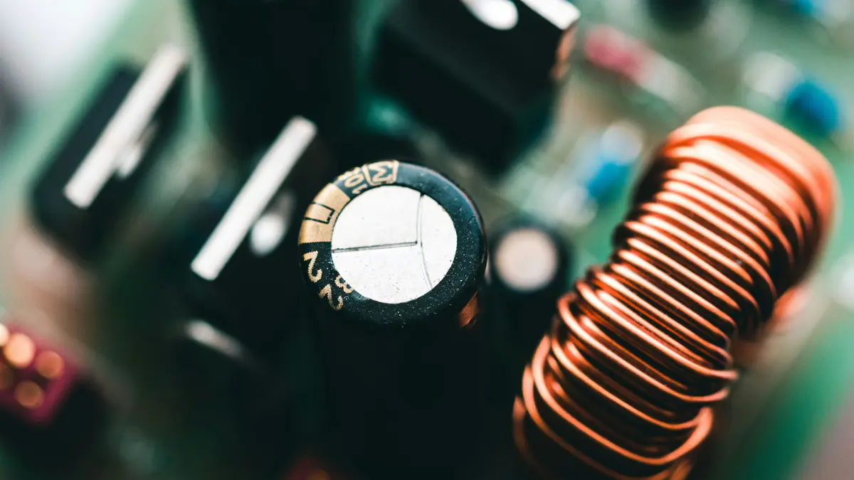
- Photo by Harrison Broadbent on Unsplash
⭐ Was this article helpful?
IDAR Mohamed
Electrical Engineer
Electrical Engineer specialized in power systems, electrical installations, and energy efficiency. Passionate about simplifying complex electrical concepts into practical guides. (University of applied sciences graduate, with experience in HV/LV systems and industrial installations.)
- AC Capacitors
- Capacitors
- Energy Storage
- Circuit Components