
I2C vs SPI: Complete Comparison Guide with Protocol Analysis & Real-World Applications
- Admin: IDAR Mohamed
- 28 Sep 2025
- 0
When designing embedded systems and IoT devices, choosing the right communication protocol can make or break your project's success. Two of the most popular serial communication protocols—I2C (Inter-Integrated Circuit) and SPI (Serial Peripheral Interface)—each offer distinct advantages for connecting microcontrollers with sensors, displays, memory devices, and other peripherals.
Understanding when to use I2C vs SPI is crucial for electrical engineers, embedded system designers, and IoT developers who need to optimize their designs for performance, cost, and reliability. This comprehensive guide will help you master both protocols and make informed decisions for your next project.
Whether you're building Arduino-based prototypes, industrial automation systems, or commercial IoT products, the choice between I2C and SPI impacts everything from PCB layout complexity to system performance and debugging capabilities.
Table of Contents
- Protocol Fundamentals
- I2C Communication Protocol
- SPI Communication Protocol
- Detailed Comparison: I2C vs SPI
- Performance Analysis
- Practical Applications
- Implementation Examples
- Troubleshooting Guide
- Best Practices
Protocol Fundamentals
Understanding Serial Communication
Both I2C and SPI are synchronous serial communication protocols, meaning they use a shared clock signal to coordinate data transfer between devices. This approach offers several advantages over asynchronous communication:
- Reliable timing: Clock synchronization eliminates timing errors
- Higher speeds: No start/stop bits required
- Error reduction: Synchronized sampling reduces data corruption
- Efficient bandwidth utilization: More data bits per transmission
Master-Slave Architecture
Both protocols implement a master-slave communication model:
- Master device: Initiates communication, generates clock signals, and controls the bus
- Slave devices: Respond to master requests and follow the master's timing
- Bus arbitration: Protocols handle multiple device access to shared communication lines
I2C Communication Protocol
I2C Protocol Overview
I2C (Inter-Integrated Circuit), developed by Philips (now NXP) in 1982, is a multi-master, multi-slave communication protocol designed for short-distance communication between integrated circuits.
I2C Hardware Requirements
I2C requires only 2 wires for communication:
| Signal | Function | Description |
|---|---|---|
| SDA | Serial Data | Bidirectional data line |
| SCL | Serial Clock | Clock signal generated by master |
| Pull-up Resistors | Signal Conditioning | Required on both SDA and SCL lines (typically 4.7kΩ) |
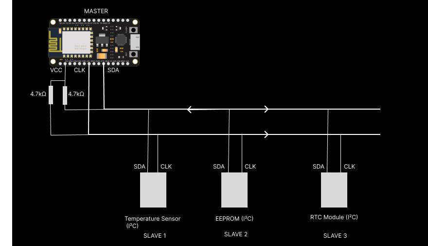
All devices share SDA and SCL lines. Each slave has a unique 7-bit address.
I2C Addressing System
I2C uses a sophisticated addressing system to communicate with multiple devices:
- 7-bit addressing: Standard mode supports 128 unique addresses (0x00-0x7F)
- 10-bit addressing: Extended mode supports 1024 addresses
- Reserved addresses: Several addresses reserved for special functions
- Address collision: Hardware resolves conflicts when multiple masters access the bus
I2C Address Format
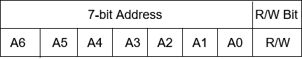
- Bits 7-1: Device address
- Bit 0: Read (1) or Write (0) operation
I2C Communication Process
1. Start Condition
- SDA transitions from HIGH to LOW while SCL is HIGH
- Indicates beginning of transmission
2. Address Phase
- Master sends 7-bit slave address + R/W bit
- Addressed slave responds with ACK (acknowledgment)
3. Data Phase
- 8-bit data bytes transmitted
- Each byte followed by ACK/NACK from receiver
4. Stop Condition
- SDA transitions from LOW to HIGH while SCL is HIGH
- Indicates end of transmission
I2C Timing Diagram
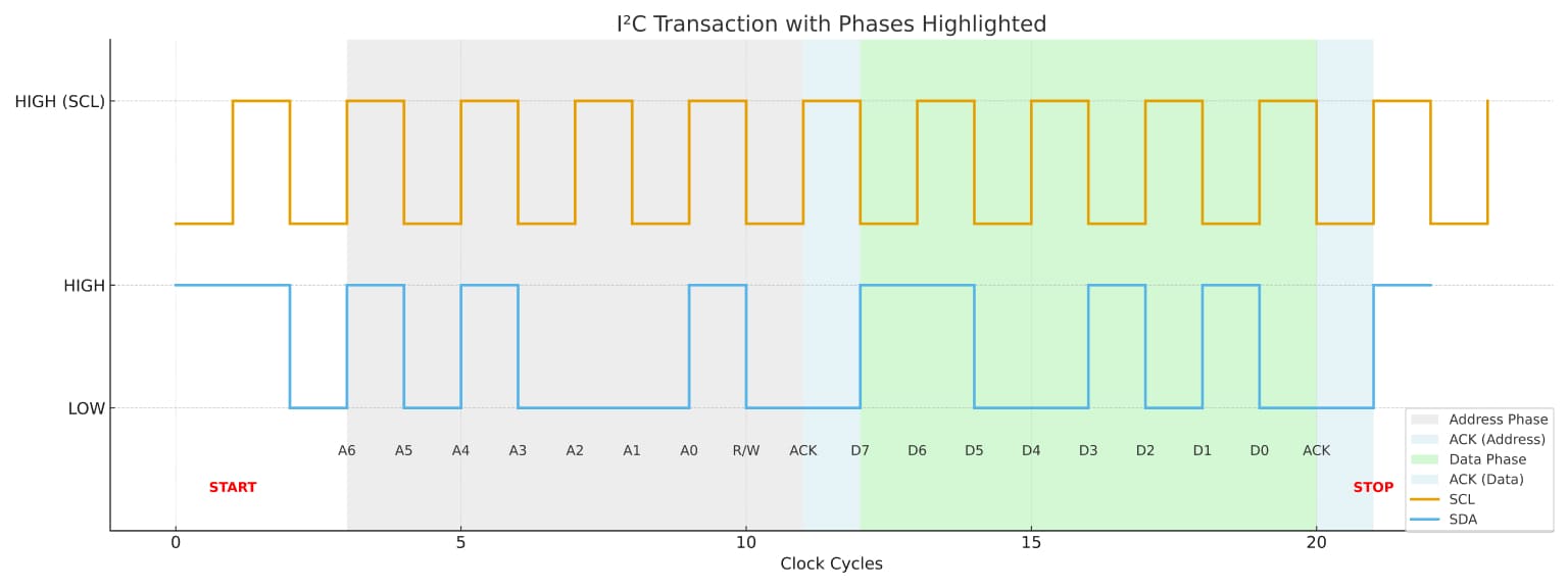
I2C communication 7-bit address with read/write bit timing diagram
I2C Speed Modes
| Mode | Maximum Speed | Application |
|---|---|---|
| Standard Mode | 100 kbps | Basic sensor communication |
| Fast Mode | 400 kbps | Display interfaces, EEPROMs |
| Fast Mode Plus | 1 Mbps | High-performance sensors |
| High Speed Mode | 3.4 Mbps | Advanced applications |
| Ultra Fast Mode | 5 Mbps | Specialized high-speed devices |
SPI Communication Protocol
SPI Protocol Overview
SPI (Serial Peripheral Interface), developed by Motorola in the 1980s, is a synchronous communication protocol designed for high-speed, short-distance communication between microcontrollers and peripheral devices.
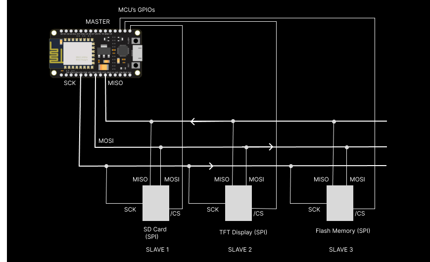
SPI Hardware Requirements
SPI requires 4 wires for basic communication:
| Signal | Alternative Names | Function | Direction |
|---|---|---|---|
| SCLK | SCK, CLK | Serial Clock | Master → All Slaves |
| MOSI | SDO, DI, SI | Master Out, Slave In | Master → Slave |
| MISO | SDI, DO, SO | Master In, Slave Out | Slave → Master |
| SS/CS | NSS, CE | Slave Select/Chip Select | Master → Individual Slave |
SPI Communication Modes
SPI supports four different communication modes based on Clock Polarity (CPOL) and Clock Phase (CPHA):
| Mode | CPOL | CPHA | Clock Polarity | Clock Phase |
|---|---|---|---|---|
| Mode 0 | 0 | 0 | Idle Low | Sample on Rising Edge |
| Mode 1 | 0 | 1 | Idle Low | Sample on Falling Edge |
| Mode 2 | 1 | 0 | Idle High | Sample on Falling Edge |
| Mode 3 | 1 | 1 | Idle High | Sample on Rising Edge |
SPI Communication Process
1. Slave Selection
- Master pulls specific SS/CS line LOW to select target slave
- Selected slave becomes active and ready for communication
2. Clock Generation
- Master generates SCLK signal at desired frequency
- Clock speed determined by master and must be compatible with slave
3. Data Exchange
- Simultaneous bidirectional data transfer
- MOSI: Master sends data to slave
- MISO: Slave sends data to master
- Data shifts on each clock edge
4. Transaction Complete
- Master pulls SS/CS HIGH to deselect slave
- Slave returns to idle state
SPI Timing Diagram (Mode 0)
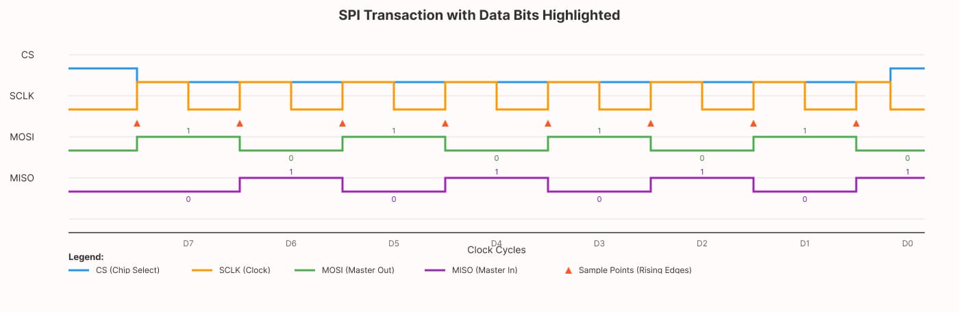
SPI communication full duplex 8-bit data transfer timing diagram
Detailed Comparison: I2C vs SPI
Hardware Complexity
| Aspect | I2C | SPI |
|---|---|---|
| Wire Count | 2 wires (+ power/ground) | 4+ wires (+ power/ground) |
| Pin Requirements | 2 pins regardless of device count | 3 + N pins (N = number of slaves) |
| Pull-up Resistors | Required (4.7kΩ typical) | Not required |
| PCB Complexity | Lower trace count, simpler routing | Higher trace count, more complex routing |
| Connector Cost | Lower (fewer pins) | Higher (more pins) |
Communication Characteristics
| Feature | I2C | SPI |
|---|---|---|
| Data Direction | Half-duplex (bidirectional on single wire) | Full-duplex (separate MOSI/MISO) |
| Addressing | Built-in 7-bit or 10-bit addressing | Hardware chip select |
| Multi-master | Supported (with arbitration) | Complex (requires additional logic) |
| Protocol Overhead | Higher (address + ACK bits) | Lower (no addressing overhead) |
| Error Detection | ACK/NACK mechanism | No built-in error detection |
Speed and Performance
| Parameter | I2C | SPI |
|---|---|---|
| Maximum Speed | 3.4 Mbps (High Speed Mode) | 50+ Mbps (implementation dependent) |
| Typical Speed | 100-400 kbps | 1-25 Mbps |
| Distance | Up to 2m (standard), 10m+ with repeaters | < 30cm (PCB), few meters with buffers |
| Capacitive Load | 400pF (standard), 50pF (high-speed) | Varies by implementation |
Device Support and Ecosystem
| Aspect | I2C | SPI |
|---|---|---|
| Device Availability | Excellent (sensors, displays, memories) | Excellent (flash, SD cards, displays) |
| Microcontroller Support | Universal | Universal |
| Bus Sharing | Multiple devices per bus | One device per chip select |
| Hot Swapping | Not supported | Not supported |
Performance Analysis
Throughput Comparison
Let's analyze actual data throughput for both protocols:
I2C Throughput Calculation
For I2C communication, consider the protocol overhead:
- Start condition: 1 bit
- Address: 8 bits (7-bit address + R/W)
- ACK: 1 bit
- Data: 8 bits
- ACK: 1 bit
- Stop condition: 1 bit
Total bits per byte: 20 bits Efficiency: 8/20 = 40%
At 400 kbps Fast Mode:
- Theoretical throughput: 400 kbps × 0.4 = 160 kbps actual data
SPI Throughput Calculation
For SPI communication:
- No addressing overhead
- No start/stop conditions
- Direct 8-bit data transfer
Total bits per byte: 8 bits Efficiency: 8/8 = 100%
At 1 MHz clock:
- Theoretical throughput: 1 Mbps × 1.0 = 1 Mbps actual data
Latency Analysis
| Protocol | Setup Time | Per-byte Overhead | Best For |
|---|---|---|---|
| I2C | Address + ACK (~20μs @ 400kHz) | High | Multiple small transactions |
| SPI | CS assertion (~1μs) | Low | Large data transfers |
Practical Applications
When to Choose I2C
Ideal Applications:
- Sensor networks: Multiple temperature, pressure, or environmental sensors
- Display interfaces: Small OLED displays, LCD character displays
- Memory devices: EEPROMs, real-time clocks with NVRAM
- Configuration interfaces: Device settings, calibration data
- IoT sensor hubs: Collecting data from multiple sensors
Example I2C System:
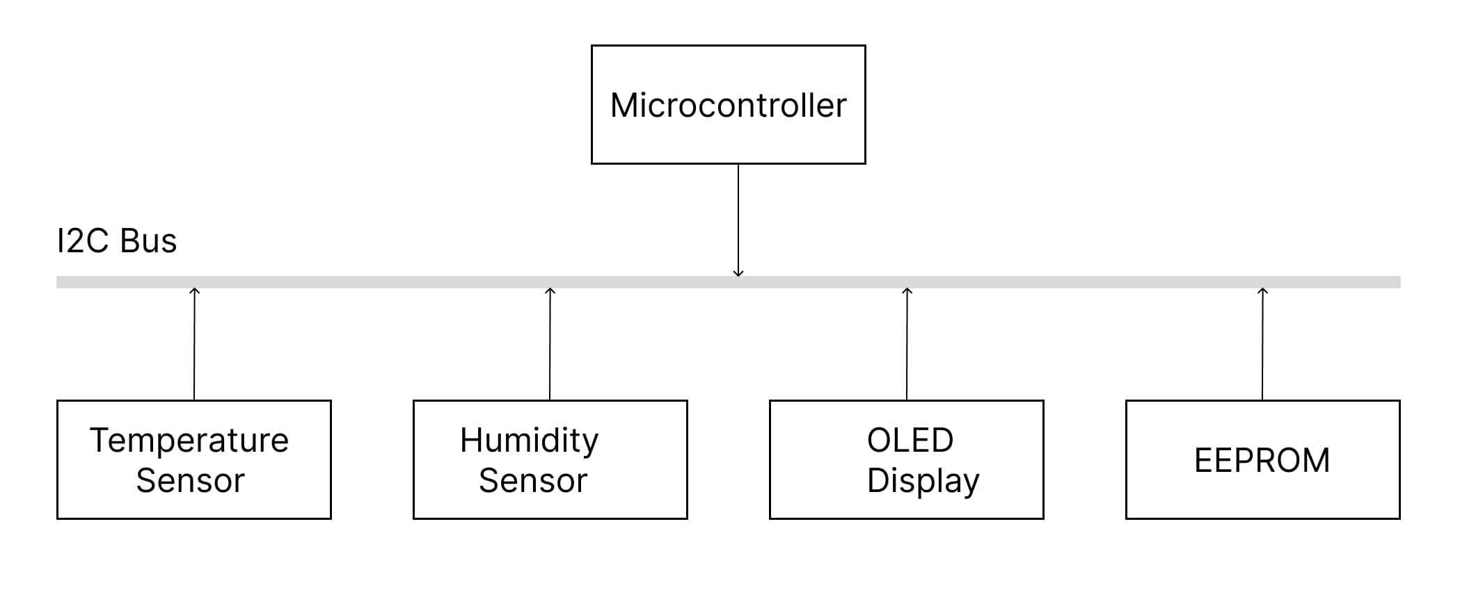
Advantages in these applications:
- Minimal pin usage
- Easy to add/remove devices
- Built-in addressing eliminates wiring complexity
- Standard sensor interfaces
When to Choose SPI
Ideal Applications:
- SD card interfaces: File system access, data logging
- Flash memory: External program storage, data storage
- Display controllers: TFT displays, e-ink screens
- ADC/DAC interfaces: High-resolution analog interfaces
- RF modules: Wireless transceivers, GPS modules
Example SPI System:
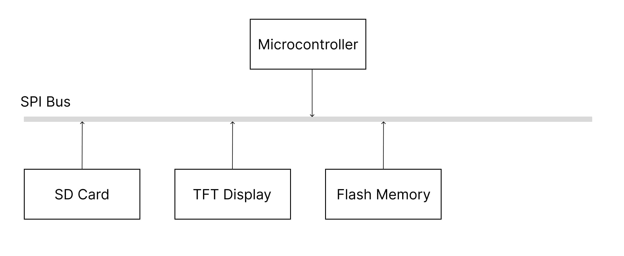
Advantages in these applications:
- High-speed data transfer
- Full-duplex communication
- Simple implementation
- Deterministic timing
Industry-Specific Use Cases
Automotive Electronics
| Application | Preferred Protocol | Reason |
|---|---|---|
| Sensor Clusters | I2C | Multiple sensors, compact wiring |
| Infotainment Storage | SPI | High-speed SD card access |
| Dashboard Displays | SPI | Fast screen updates |
| Configuration Memory | I2C | Easy addressing, moderate speed |
Industrial Automation
| Application | Preferred Protocol | Reason |
|---|---|---|
| Sensor Networks | I2C | Multi-drop capability |
| HMI Displays | SPI | Fast graphics updates |
| Data Logging | SPI | High-speed storage access |
| Device Configuration | I2C | Simple addressing |
Consumer Electronics
| Application | Preferred Protocol | Reason |
|---|---|---|
| Smart Home Sensors | I2C | Pin efficiency, multiple devices |
| Camera Modules | SPI | High-speed image data |
| Audio Codecs | I2C | Configuration, SPI for audio data |
| Memory Cards | SPI | Standard interface |
Implementation Examples
Arduino I2C Example
#include <Wire.h>

// I2C Temperature Sensor (LM75A)
#define TEMP_SENSOR_ADDR 0x48

void setup() {
  Serial.begin(9600);
  Wire.begin(); // Initialize I2C as master
  Serial.println("I2C Temperature Sensor Test");
}

void loop() {
  float temperature = readTemperature();

  Serial.print("Temperature: ");
  Serial.print(temperature);
  Serial.println(" °C");

  delay(1000);
}

float readTemperature() {
  // Request 2 bytes from temperature sensor
  Wire.requestFrom(TEMP_SENSOR_ADDR, 2);

  if (Wire.available() >= 2) {
    uint8_t msb = Wire.read();
    uint8_t lsb = Wire.read();

    // Convert to temperature (LM75A format)
    int16_t tempRaw = (msb << 8) | lsb;
    tempRaw >>= 5; // Right shift to get 11-bit value

    return tempRaw * 0.125; // 0.125°C per LSB
  }

  return -999; // Error value
}

// Writing to I2C device
void writeToDevice(uint8_t address, uint8_t reg, uint8_t data) {
  Wire.beginTransmission(address);
  Wire.write(reg);    // Register address
  Wire.write(data);   // Data to write
  uint8_t error = Wire.endTransmission();

  if (error == 0) {
    Serial.println("Write successful");
  } else {
    Serial.println("Write failed");
  }
}
Arduino SPI Example
#include <SPI.h>

// SPI Flash Memory (W25Q32)
#define FLASH_CS_PIN 10
#define CMD_READ_ID  0x9F
#define CMD_READ_DATA 0x03

void setup() {
  Serial.begin(9600);

  // Initialize SPI
  SPI.begin();
  pinMode(FLASH_CS_PIN, OUTPUT);
  digitalWrite(FLASH_CS_PIN, HIGH); // Deselect initially

  // Configure SPI settings
  SPI.beginTransaction(SPISettings(1000000, MSBFIRST, SPI_MODE0));

  Serial.println("SPI Flash Memory Test");
  readFlashID();
}

void loop() {
  // Read first 16 bytes from flash
  readFlashData(0x000000, 16);
  delay(2000);
}

void readFlashID() {
  digitalWrite(FLASH_CS_PIN, LOW);  // Select device

  SPI.transfer(CMD_READ_ID);        // Send read ID command

  uint8_t manufacturer = SPI.transfer(0x00);
  uint8_t deviceType = SPI.transfer(0x00);
  uint8_t deviceID = SPI.transfer(0x00);

  digitalWrite(FLASH_CS_PIN, HIGH); // Deselect device

  Serial.print("Manufacturer ID: 0x");
  Serial.println(manufacturer, HEX);
  Serial.print("Device Type: 0x");
  Serial.println(deviceType, HEX);
  Serial.print("Device ID: 0x");
  Serial.println(deviceID, HEX);
}

void readFlashData(uint32_t address, uint16_t length) {
  digitalWrite(FLASH_CS_PIN, LOW);  // Select device

  // Send read command and 24-bit address
  SPI.transfer(CMD_READ_DATA);
  SPI.transfer((address >> 16) & 0xFF);
  SPI.transfer((address >> 8) & 0xFF);
  SPI.transfer(address & 0xFF);

  Serial.print("Data at address 0x");
  Serial.print(address, HEX);
  Serial.print(": ");

  // Read data bytes
  for (uint16_t i = 0; i < length; i++) {
    uint8_t data = SPI.transfer(0x00);
    Serial.print("0x");
    if (data < 0x10) Serial.print("0");
    Serial.print(data, HEX);
    Serial.print(" ");
  }

  digitalWrite(FLASH_CS_PIN, HIGH); // Deselect device
  Serial.println();
}

// SPI configuration for different devices
void configureSPIForDevice(uint8_t mode, uint32_t speed) {
  SPI.endTransaction();
  SPI.beginTransaction(SPISettings(speed, MSBFIRST, mode));
}
ESP32 Advanced Example
// ESP32 with both I2C and SPI
#include <Wire.h>
#include <SPI.h>

// I2C Configuration
#define I2C_SDA 21
#define I2C_SCL 22
#define I2C_FREQ 400000

// SPI Configuration
#define SPI_MOSI 23
#define SPI_MISO 19
#define SPI_CLK  18
#define SPI_CS   5

void setup() {
  Serial.begin(115200);

  // Initialize I2C with custom pins
  Wire.begin(I2C_SDA, I2C_SCL);
  Wire.setClock(I2C_FREQ);

  // Initialize SPI with custom pins
  SPI.begin(SPI_CLK, SPI_MISO, SPI_MOSI, SPI_CS);

  Serial.println("ESP32 Dual Protocol Example Ready");
}

void loop() {
  // Use both protocols in same system
  scanI2CDevices();
  delay(1000);
  testSPILoopback();
  delay(2000);
}

void scanI2CDevices() {
  Serial.println("Scanning I2C bus...");
  uint8_t deviceCount = 0;

  for (uint8_t addr = 1; addr < 127; addr++) {
    Wire.beginTransmission(addr);
    uint8_t error = Wire.endTransmission();

    if (error == 0) {
      Serial.print("Device found at address 0x");
      if (addr < 16) Serial.print("0");
      Serial.println(addr, HEX);
      deviceCount++;
    }
  }

  if (deviceCount == 0) {
    Serial.println("No I2C devices found");
  }
}

void testSPILoopback() {
  // Connect MOSI to MISO for loopback test
  digitalWrite(SPI_CS, LOW);

  uint8_t testData = 0xAA;
  uint8_t received = SPI.transfer(testData);

  digitalWrite(SPI_CS, HIGH);

  Serial.print("SPI Loopback - Sent: 0x");
  Serial.print(testData, HEX);
  Serial.print(", Received: 0x");
  Serial.println(received, HEX);
}
Troubleshooting Guide
Common I2C Issues
1. No ACK Response
Symptoms: Device not responding, Wire.endTransmission() returns error code Causes & Solutions:
- Wrong address: Verify device address with datasheet
- Missing pull-ups: Add 4.7kΩ resistors to SDA and SCL
- Power issues: Check device power supply
- Wiring errors: Verify SDA/SCL connections
//Include wire library
#include <Wire.h>

// I2C Configuration
#define I2C_SDA 21
#define I2C_SCL 22
#define I2C_FREQ 400000

void setup() {
  Serial.begin(115200);

  // Initialize I2C with custom pins
  Wire.begin(I2C_SDA, I2C_SCL);
  Wire.setClock(I2C_FREQ);
}

void loop() {
  scanI2C();
  delay(1000);
}

// I2C Device Scanner
void scanI2C() {
  for (uint8_t addr = 1; addr < 127; addr++) {
    Wire.beginTransmission(addr);
    uint8_t error = Wire.endTransmission();

    if (error == 0) {
      Serial.print("Found device at 0x");
      Serial.println(addr, HEX);
    }
  }
}
2. Bus Lockup
Symptoms: Communication stops working, bus stuck LOW Solutions:
- Clock stretching timeout: Increase I2C timeout
- Software reset: Reset I2C peripheral
- Bus recovery: Generate clock pulses to free stuck slave
3. Speed Issues
Symptoms: Intermittent communication failures Solutions:
- Reduce clock speed: Lower from 400kHz to 100kHz
- Check capacitance: Reduce wire length, check pull-up values
- Signal integrity: Use oscilloscope to verify waveforms
Common SPI Issues
1. No Data Transfer
Symptoms: MISO always reads 0x00 or 0xFF Causes & Solutions:
- Clock mode mismatch: Verify CPOL/CPHA settings
- CS timing: Check chip select assertion/deassertion
- Wiring errors: Verify MOSI/MISO, SCLK connections
- Clock speed: Reduce speed for initial testing
#include <SPI.h>

// SPI Configuration
#define SPI_MOSI 23
#define SPI_MISO 19
#define SPI_CLK  18
#define SPI_CS   5

void setup() {
  Serial.begin(115200);

  // Initialize SPI with custom pins
  SPI.begin(SPI_CLK, SPI_MISO, SPI_MOSI, SPI_CS);
}

void loop() {
  testSPIModes();
  delay(2000);
}

// SPI Configuration Test
void testSPIModes() {
  uint8_t modes[] = {SPI_MODE0, SPI_MODE1, SPI_MODE2, SPI_MODE3};

  for (int i = 0; i < 4; i++) {
    SPI.beginTransaction(SPISettings(1000000, MSBFIRST, modes[i]));

    digitalWrite(CS_PIN, LOW);
    uint8_t response = SPI.transfer(0x9F); // Read ID command
    digitalWrite(CS_PIN, HIGH);

    Serial.print("Mode ");
    Serial.print(i);
    Serial.print(": 0x");
    Serial.println(response, HEX);

    SPI.endTransaction();
  }
}
2. Data Corruption
Symptoms: Inconsistent data, wrong values Solutions:
- Clock stability: Use stable clock source
- Signal integrity: Reduce wire length, add ground planes
- CS timing: Ensure proper setup/hold times
- Power decoupling: Add bypass capacitors
3. Multiple Device Issues
Symptoms: Devices interfere with each other Solutions:
- Individual CS lines: Use separate chip select for each device
- Tri-state outputs: Verify devices properly disconnect MISO
- Bus contention: Check for multiple drivers
Debug Tools and Techniques
Hardware Tools
- Logic Analyzer: Capture and analyze protocol timing
- Oscilloscope: Verify signal integrity and timing
- Multimeter: Check power supplies and pull-up resistors
- Protocol Decoder: Software analysis of captured signals
Software Debug Techniques
#include <Wire.h>
#include <SPI.h>

// I2C Configuration
#define I2C_SDA 21
#define I2C_SCL 22
#define I2C_FREQ 400000

// SPI Configuration
#define SPI_MOSI 23
#define SPI_MISO 19
#define SPI_CLK  18
#define SPI_CS   5

void setup() {
  Serial.begin(115200);

  // Initialize I2C with custom pins
  Wire.begin(I2C_SDA, I2C_SCL);
  Wire.setClock(I2C_FREQ);

  // Initialize SPI with custom pins
  SPI.begin(SPI_CLK, SPI_MISO, SPI_MOSI, SPI_CS);
}

void loop() {
  debugI2C();
  delay(1000);
  debugSPI();
  delay(2000);
}

// I2C Debug Function
void debugI2C(uint8_t address, uint8_t reg) {
  Serial.print("Reading from device 0x");
  Serial.print(address, HEX);
  Serial.print(", register 0x");
  Serial.println(reg, HEX);

  Wire.beginTransmission(address);
  Wire.write(reg);
  uint8_t error = Wire.endTransmission();

  if (error != 0) {
    Serial.print("Transmission error: ");
    Serial.println(error);
    return;
  }

  Wire.requestFrom(address, (uint8_t)1);

  if (Wire.available()) {
    uint8_t data = Wire.read();
    Serial.print("Data: 0x");
    Serial.println(data, HEX);
  } else {
    Serial.println("No data available");
  }
}

// SPI Debug Function
void debugSPI(uint8_t command) {
  Serial.print("SPI Command: 0x");
  Serial.println(command, HEX);

  digitalWrite(CS_PIN, LOW);
  delayMicroseconds(10); // CS setup time

  uint8_t response = SPI.transfer(command);

  delayMicroseconds(10); // CS hold time
  digitalWrite(CS_PIN, HIGH);

  Serial.print("Response: 0x");
  Serial.println(response, HEX);
}
Best Practices
I2C Best Practices
Hardware Design
- Pull-up resistors: Use 4.7kΩ for standard speeds, 2.2kΩ for higher speeds
- Bus capacitance: Keep total capacitance under 400pF for standard mode
- Power supply: Use clean, stable power with proper decoupling
- EMI protection: Use twisted pairs or shielded cables for longer distances
Software Implementation
- Error handling: Always check Wire.endTransmission() return codes
- Timeout handling: Implement timeouts for communication
- Address validation: Verify device addresses before communication
- Bus recovery: Implement bus recovery mechanisms
// Robust I2C Read Function
bool readI2CDevice(uint8_t address, uint8_t reg, uint8_t* data, uint8_t length) {
  // Start transmission
  Wire.beginTransmission(address);
  Wire.write(reg);

  uint8_t error = Wire.endTransmission();
  if (error != 0) {
    Serial.print("I2C transmission error: ");
    Serial.println(error);
    return false;
  }

  // Request data
  uint8_t received = Wire.requestFrom(address, length);
  if (received != length) {
    Serial.println("I2C: Incorrect number of bytes received");
    return false;
  }

  // Read data
  for (uint8_t i = 0; i < length; i++) {
    if (Wire.available()) {
      data[i] = Wire.read();
    } else {
      Serial.println("I2C: No more data available");
      return false;
    }
  }

  return true;
}

// I2C Bus Recovery
void recoverI2CBus() {
  pinMode(SDA_PIN, OUTPUT);
  pinMode(SCL_PIN, OUTPUT);

  // Generate clock pulses to free stuck slave
  for (int i = 0; i < 9; i++) {
    digitalWrite(SCL_PIN, HIGH);
    delayMicroseconds(5);
    digitalWrite(SCL_PIN, LOW);
    delayMicroseconds(5);
  }

  // Generate stop condition
  digitalWrite(SDA_PIN, LOW);
  delayMicroseconds(5);
  digitalWrite(SCL_PIN, HIGH);
  delayMicroseconds(5);
  digitalWrite(SDA_PIN, HIGH);
  delayMicroseconds(5);

  // Reinitialize I2C
  Wire.begin();
}
SPI Best Practices
Hardware Design
- Short traces: Keep SPI traces as short as possible
- Ground planes: Use solid ground planes for signal integrity
- Decoupling: Place bypass capacitors close to ICs
- Clock distribution: Use star topology for clock distribution to multiple slaves
Software Implementation
- CS timing: Ensure proper chip select timing
- Clock configuration: Verify clock polarity and phase
- Speed optimization: Start with low speeds, increase gradually
- Error detection: Implement checksums for critical data
// Robust SPI Transaction Function
bool spiTransaction(uint8_t* txData, uint8_t* rxData, uint16_t length) {
  // Configure SPI settings
  SPI.beginTransaction(SPISettings(1000000, MSBFIRST, SPI_MODE0));

  // Assert chip select
  digitalWrite(CS_PIN, LOW);
  delayMicroseconds(1); // CS setup time

  // Transfer data
  for (uint16_t i = 0; i < length; i++) {
    rxData[i] = SPI.transfer(txData[i]);
  }

  // Deassert chip select
  delayMicroseconds(1); // CS hold time
  digitalWrite(CS_PIN, HIGH);

  SPI.endTransaction();

  return true;
}

// SPI Device Configuration
struct SPIConfig {
  uint32_t clockSpeed;
  uint8_t bitOrder;
  uint8_t dataMode;
  uint8_t csPin;
};

void configureSPIDevice(const SPIConfig& config) {
  pinMode(config.csPin, OUTPUT);
  digitalWrite(config.csPin, HIGH);

  SPI.beginTransaction(SPISettings(
    config.clockSpeed,
    config.bitOrder,
    config.dataMode
  ));
}
Power Management Considerations
I2C Power Optimization
- Clock stretching: Use to accommodate slow devices
- Dynamic addressing: Disable unused devices
- Low power modes: Put devices in sleep mode when not in use
// I2C Power Management
void setI2CDevicePowerMode(uint8_t address, uint8_t powerReg, bool lowPower) {
  Wire.beginTransmission(address);
  Wire.write(powerReg);
  Wire.write(lowPower ? 0x01 : 0x00);
  Wire.endTransmission();
}
SPI Power Optimization
- CS management: Keep devices deselected when not in use
- Clock gating: Disable SPI clock when not needed
- Device sleep: Put SPI devices in sleep mode
Signal Integrity Guidelines
I2C Signal Integrity
- Rise time: Ensure proper rise times (< 1μs for standard mode)
- Bus loading: Calculate total bus capacitance
- Noise immunity: Use proper filtering and shielding
SPI Signal Integrity
- Clock quality: Maintain clean clock signals
- Skew management: Match trace lengths for clock and data
- Termination: Use proper termination for high speeds
Advanced Topics
Multi-Master I2C Systems
I2C supports multiple masters on the same bus through built-in arbitration:
// Multi-master I2C implementation
class I2CMaster {
private:
  uint8_t masterID;
  bool busAvailable;

public:
  I2CMaster(uint8_t id) : masterID(id), busAvailable(true) {}

  bool requestBus() {
    // Check if bus is available
    if (!busAvailable) {
      return false;
    }

    // Attempt to gain bus access
    Wire.beginTransmission(0x00); // General call address
    uint8_t error = Wire.endTransmission();

    if (error == 0) {
      busAvailable = false;
      return true;
    }

    return false;
  }

  void releaseBus() {
    busAvailable = true;
  }
};
High-Speed SPI Optimization
For maximum SPI performance:
// High-speed SPI with DMA (ESP32 example)
#include "driver/spi_master.h"

spi_device_handle_t spiDevice;

void initHighSpeedSPI() {
  spi_bus_config_t busConfig = {
    .mosi_io_num = 23,
    .miso_io_num = 19,
    .sclk_io_num = 18,
    .quadwp_io_num = -1,
    .quadhd_io_num = -1,
    .max_transfer_sz = 4096
  };

  spi_device_interface_config_t deviceConfig = {
    .clock_speed_hz = 10000000, // 10MHz
    .mode = 0,
    .spics_io_num = 5,
    .queue_size = 7
  };

  spi_bus_initialize(SPI2_HOST, &busConfig, 1);
  spi_bus_add_device(SPI2_HOST, &deviceConfig, &spiDevice);
}

void highSpeedTransfer(uint8_t* data, size_t length) {
  spi_transaction_t transaction = {
    .length = length * 8,
    .tx_buffer = data,
    .rx_buffer = data
  };

  spi_device_transmit(spiDevice, &transaction);
}
Protocol Bridging
Sometimes you need to bridge between I2C and SPI:
// I2C to SPI Bridge
class ProtocolBridge {
private:
  uint8_t i2cAddress;
  uint8_t spiCS;

public:
  ProtocolBridge(uint8_t i2cAddr, uint8_t cs)
    : i2cAddress(i2cAddr), spiCS(cs) {}

  void bridgeCommand(uint8_t command, uint8_t* data, uint8_t length) {
    // Receive command via I2C
    Wire.onReceive([this](int bytes) {
      if (bytes >= 2) {
        uint8_t cmd = Wire.read();
        uint8_t len = Wire.read();
        uint8_t buffer[len];

        for (int i = 0; i < len; i++) {
          buffer[i] = Wire.read();
        }

        // Forward to SPI device
        forwardToSPI(cmd, buffer, len);
      }
    });
  }

private:
  void forwardToSPI(uint8_t command, uint8_t* data, uint8_t length) {
    digitalWrite(spiCS, LOW);
    SPI.transfer(command);

    for (uint8_t i = 0; i < length; i++) {
      SPI.transfer(data[i]);
    }

    digitalWrite(spiCS, HIGH);
  }
};
Decision Matrix: Choosing the Right Protocol
Use this decision matrix to select the optimal protocol for your project:
Project Requirements Assessment
| Factor | Weight | I2C Score (1-5) | SPI Score (1-5) | Comments |
|---|---|---|---|---|
| Pin Efficiency | High | 5 | 2 | I2C uses only 2 pins |
| Speed Requirements | Medium | 2 | 5 | SPI much faster |
| Multiple Devices | High | 5 | 3 | I2C handles addressing automatically |
| Implementation Simplicity | Medium | 3 | 4 | SPI simpler protocol |
| Error Handling | High | 4 | 2 | I2C has built-in ACK/NACK |
| Distance | Low | 4 | 2 | I2C better for longer distances |
Application-Specific Recommendations
IoT Sensor Networks
Recommendation: I2C
- Multiple sensors on same bus
- Pin efficiency crucial
- Moderate speed requirements
- Built-in addressing simplifies wiring
High-Performance Data Acquisition
Recommendation: SPI
- High-speed ADCs
- Large data transfers
- Deterministic timing required
- Full-duplex communication beneficial
Mixed-Signal Applications
Recommendation: Both
- I2C for configuration and slow sensors
- SPI for high-speed data and storage
- Optimize each interface for its purpose
Future Developments and Trends
I2C Evolution
I3C (Improved Inter-Integrated Circuit)
- Higher speeds: Up to 12.5 Mbps
- Lower power: Dynamic voltage scaling
- Backward compatibility: Works with existing I2C devices
- In-band interrupts: Eliminates need for separate interrupt lines
I2C Extensions
- SMBus compatibility: Enhanced power management features
- PMBus support: Power management applications
- HDMI CEC: Consumer electronics control
SPI Advancements
Quad SPI (QSPI)
- 4-bit data transfer: MOSI, MISO, WP, HOLD
- Higher throughput: 4x data rate improvement
- Memory applications: Flash memory interfaces
Dual SPI
- 2-bit data transfer: Increased bandwidth
- Cost-effective: Better than QSPI for many applications
Emerging Alternatives
CAN Bus
- Automotive applications: Robust communication
- Differential signaling: Better noise immunity
- Multi-master: Built-in arbitration
USB-C and USB4
- High-speed serial: Gbps data rates
- Power delivery: Integrated power management
- Versatile connectivity: Replaces many protocols
Conclusion: Making the Right Choice
The choice between I2C and SPI ultimately depends on your specific application requirements, system constraints, and performance needs. Both protocols have stood the test of time and continue to be essential tools in the embedded systems designer's toolkit.
Choose I2C when you need:
- Maximum pin efficiency with multiple devices
- Built-in addressing and error handling
- Moderate speeds with good noise immunity
- Simple wiring and easy debugging
- Standard sensor interfaces
Choose SPI when you need:
- High-speed data transfer capabilities
- Full-duplex communication
- Simple, deterministic protocol behavior
- Maximum throughput for data-intensive applications
- Direct memory access (DMA) compatibility
Consider both protocols when:
- Building complex systems with diverse requirements
- Optimizing each interface for specific tasks
- Balancing performance and resource utilization
- Supporting legacy devices and future expansion
Remember that many successful embedded systems use both protocols strategically—I2C for sensor networks and configuration interfaces, SPI for high-performance data transfer and storage. The key is understanding each protocol's strengths and applying them where they provide the greatest benefit.
As embedded systems continue to evolve toward higher performance and greater connectivity, both I2C and SPI will remain fundamental building blocks, supplemented by newer protocols like I3C and advanced SPI variants. Master both protocols, understand their trade-offs, and you'll be well-equipped to design robust, efficient embedded systems for any application.
🔗 Related Posts
- Understanding Smart Grids: Revolutionizing Energy Distribution
- A Comprehensive Guide to IoT Devices
- Mastering PCB Design: Techniques, and Best Practices
- Variable Frequency Drive (VFD): The Complete Guide
Helpful Tools and Calculators
- Resistor Color Code Calculator
- Ohm's Law Calculator
- Wire Size Calculator: Complete Guide
- Voltage Drop Calculator
Credits
-
Photo by Kumpan Electric on Unsplash
⭐ Was this article helpful?
IDAR Mohamed
Electrical Engineer
Electrical Engineer specialized in power systems, electrical installations, and energy efficiency. Passionate about simplifying complex electrical concepts into practical guides. (University of applied sciences graduate, with experience in HV/LV systems and industrial installations.)
- I2C Communication
- SPI Protocol
- Serial Communication
- Embedded Systems