

Understanding Electrical Resistance: Complete Guide with Calculations and Real-World Examples
- Admin: IDAR Mohamed
- 27 Sep 2025
- 0
Have you ever wondered why your smartphone charger gets warm when charging, or why some electrical devices need thicker wires than others? The answer lies in a fundamental electrical property called resistance - a concept that governs how electrical current flows through every circuit, from the simplest flashlight to complex industrial systems.
Understanding electrical resistance is essential for anyone working with electronics, designing circuits, or simply wanting to grasp how electricity behaves in the real world. This guide will teach you not just what resistance is, but how to calculate it, measure it, and apply it to solve practical electrical problems.
Whether you're an engineering student, electronics hobbyist, or professional electrician, mastering resistance calculations will help you design better circuits, troubleshoot problems effectively, and understand why electrical systems behave the way they do.
What is Electrical Resistance?
Electrical resistance is the opposition that a material presents to the flow of electric current. Think of it like friction in mechanical systems - just as friction opposes motion, resistance opposes the flow of electrons through a conductor.
When electrons move through any material, they collide with atoms, impurities, and crystal boundaries. These collisions convert some of the electrical energy into heat energy, which is why resistors get warm and why power lines lose energy over long distances.
The Mathematical Foundation: Ohm's Law
The relationship between voltage, current, and resistance is described by Ohm's Law:
Where:
- V = Voltage (volts)
- I = Current (amperes)
- R = Resistance (ohms, Ω)
This can be rearranged to solve for any variable:
- Current:
- Resistance:
Power Dissipation in Resistive Elements
When current flows through resistance, electrical energy is converted to heat. The power dissipated is calculated using:
Key insight: Power increases with the square of current, making current the most critical factor in heating calculations.
Factors That Determine Resistance
1. Material Properties (Resistivity)
Different materials have inherently different abilities to conduct electricity, quantified by their resistivity (ρ):
| Material | Resistivity (Ω·m) | Application |
|---|---|---|
| Silver | 1.59 × 10⁻⁸ | Premium contacts |
| Copper | 1.68 × 10⁻⁸ | Standard wiring |
| Aluminum | 2.82 × 10⁻⁸ | Power transmission |
| Iron | 9.71 × 10⁻⁸ | Magnetic applications |
| Nichrome | 1.10 × 10⁻⁶ | Heating elements |
| Carbon | 3.50 × 10⁻⁵ | Resistors |
2. Physical Dimensions
The resistance of any conductor depends on its geometry according to:
Where:
- ρ = Material resistivity
- L = Length of conductor
- A = Cross-sectional area
Practical implications:
- Longer conductors: Higher resistance
- Thicker conductors: Lower resistance
- Material choice: Dramatically affects resistance
3. Temperature Effects
Most materials' resistance changes with temperature. For metals, the relationship is approximately linear:
Where:
- = Resistance at temperature T
- = Resistance at 20°C
- α = Temperature coefficient (0.004/°C for copper)
Step-by-Step Resistance Calculations
Example 1: Basic Circuit Analysis
Given: 12V battery connected to a 4Ω resistor
Step 1 - Calculate Current (Ohm's Law):
Step 2 - Calculate Power Dissipation:
Step 3 - Verify Using Alternative Power Formula: ✓
Example 2: Wire Resistance Calculation
Scenario: Calculate the resistance of 100 feet of 12 AWG copper wire
Given Data:
- Length: 100 feet = 30.48 meters
- 12 AWG diameter: 2.05 mm, Area: 3.31 mm²
- Copper resistivity: 1.68 × 10⁻⁸ Ω·m
Step 1 - Convert Units: Area = 3.31 mm² = 3.31 × 10⁻⁶ m²
Step 2 - Apply Resistance Formula:
Result: 100 feet of 12 AWG copper wire has 0.155Ω resistance
Example 3: Series Resistance Circuit
Given: Three resistors in series: 10Ω, 15Ω, and 5Ω connected to 24V source
Step 1 - Calculate Total Resistance:
Step 2 - Calculate Circuit Current:
Step 3 - Calculate Individual Voltage Drops:
Step 4 - Verify Kirchhoff's Voltage Law: ✓
Example 4: Parallel Resistance Circuit
Given: Three resistors in parallel: 6Ω, 12Ω, and 4Ω connected to 12V source
Step 1 - Calculate Total Resistance:
Step 2 - Calculate Total Current:
Step 3 - Calculate Individual Branch Currents:
Step 4 - Verify Kirchhoff's Current Law: ✓
Temperature Effects on Resistance
Temperature Coefficient Calculations
Example: Copper wire resistance at different temperatures
Given: 100m of copper wire with 1Ω resistance at 20°C
At 75°C (operating temperature):
Impact: 22% increase in resistance due to temperature rise
Practical Temperature Considerations
Why temperature matters:
- Motor windings: Resistance increases as motors heat up during operation
- Power transmission: Line losses increase in hot weather
- Electronic components: Performance changes with temperature
- Heating elements: Designed to operate at high temperatures safely
Real-World Applications of Resistance Calculations
1. Heating Element Design
Electric water heater element calculation:
Requirements: 4500W heating element for 240V supply
Step 1 - Calculate Required Resistance:
Step 2 - Calculate Operating Current:
Step 3 - Verify Power Calculation: ✓
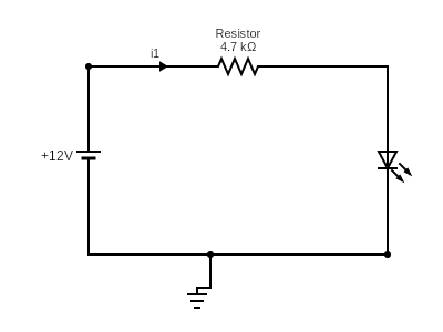
2. LED Current Limiting Resistor
Problem: Calculate resistor value for LED circuit
Given:
- Supply voltage: 12V
- LED forward voltage: 2.1V
- Desired LED current: 20mA
Step 1 - Calculate Voltage Drop Across Resistor:
Step 2 - Calculate Required Resistance:
Step 3 - Select Standard Resistor Value: Use 470Ω (closest standard value)
Step 4 - Calculate Actual Current: (acceptable)
3. Voltage Drop Analysis
Scenario: 200-foot cable run for 120V, 15A load
Given: 12 AWG copper wire (1.6Ω/1000ft resistance)
Step 1 - Calculate Cable Resistance: Round trip distance: 200 × 2 = 400 feet
Step 2 - Calculate Voltage Drop:
Step 3 - Calculate Load Voltage:
Step 4 - Calculate Percentage Drop:
Conclusion: 8% voltage drop exceeds acceptable limits (typically 3-5%), requiring larger wire size.
Advanced Resistance Concepts
AC Impedance vs DC Resistance
At higher frequencies, conductors exhibit impedance rather than simple resistance:
Where:
- Z = Impedance (ohms)
- R = Resistance (real component)
- X = Reactance (imaginary component)
- j = Imaginary unit
Skin Effect: At high frequencies, current concentrates near the conductor surface, effectively reducing the cross-sectional area and increasing resistance.
Superconductivity
Some materials exhibit zero electrical resistance below a critical temperature:
- Type I superconductors: Elements like mercury, lead
- Type II superconductors: Compounds like YBCO ceramics
- Applications: MRI magnets, power transmission research
- Limitation: Require cryogenic cooling systems
Measuring Resistance in Practice
Using a Digital Multimeter
Procedure for resistance measurement:
- Power off the circuit completely
- Isolate the component from the circuit
- Select ohms range on multimeter
- Connect probes across the component
- Read resistance value directly
Common Measurement Errors
Error sources:
- Parallel paths: Other circuit components affecting reading
- Contact resistance: Poor probe connections
- Temperature effects: Component heating during measurement
- Range selection: Using inappropriate measurement range
Troubleshooting with Resistance Measurements
Typical resistance values:
- Good wire connections: <0.1Ω
- Heating elements: 10-50Ω when cold
- Motor windings: 1-20Ω typically
- Open circuits: Infinite resistance (OL display)
- Short circuits: Near zero resistance
Conclusion: Mastering Electrical Resistance
Understanding electrical resistance and its calculations is fundamental to working with any electrical or electronic system. From designing simple LED circuits to analyzing complex power distribution systems, resistance determines how current flows, how much power is consumed, and how components behave under different conditions.
Key principles to remember:
- Ohm's Law governs the relationship between voltage, current, and resistance
- Power dissipation increases with the square of current (P = I²R)
- Temperature significantly affects resistance in most materials
- Series circuits add resistances, parallel circuits reduce total resistance
- Material properties and physical dimensions determine resistance values
Whether you're calculating voltage drops in wire runs, selecting current-limiting resistors, or designing heating elements, these fundamental concepts and calculation methods will serve as your foundation for electrical analysis and design.
Ready to apply these concepts? Start by practicing with simple circuits and gradually work up to more complex applications. The mathematical relationships are straightforward, but the practical applications are virtually limitless.
For advanced circuit analysis techniques, explore our guides on Kirchhoff's Laws and AC circuit analysis.
🔗 Related Posts
- Kirchhoff's Laws: Complete Guide with Circuit Analysis Examples
- Understanding Electric Current: A Comprehensive Guide
- Complete Guide to Voltage Drop: Calculations, Tables & Calculators
- AC Capacitors: Types, Functionality, and Applications
Helpful Calculators
- Ohm's Law Calculator
- Resistor Color Code Calculator
- Series Parallel Resistance Calculator
- Voltage Drop Calculator
Credits
- Photo by Angeles Pérez on Unsplash
⭐ Was this article helpful?
IDAR Mohamed
Electrical Engineer
Electrical Engineer specialized in power systems, electrical installations, and energy efficiency. Passionate about simplifying complex electrical concepts into practical guides. (University of applied sciences graduate, with experience in HV/LV systems and industrial installations.)
- Electrical Resistance
- Ohm's Law
- Circuit Calculations
- Electrical Theory