Conduit Fill Chart & Calculations: Complete NEC Guide with Wire Capacity Tables
- Admin: IDAR Mohamed
- 27 Oct 2025
- 0
Proper conduit fill is critical for electrical safety, code compliance, and system performance. Overfilling conduits causes excessive heat buildup, difficult wire pulling, and potential insulation damage, while oversizing wastes money and installation space. Understanding NEC conduit fill requirements ensures your electrical installations are safe, compliant, and efficient.
Whether you're installing residential branch circuits, commercial power distribution, or industrial control wiring, mastering conduit fill calculations is essential for every electrical professional. This guide provides the charts, calculations, and practical examples you need to size conduits correctly every time.
Table of Contents
- Understanding Conduit Fill Requirements
- NEC Conduit Fill Tables and Charts
- Step-by-Step Conduit Fill Calculations
- Quick Reference Wire Fill Charts
- Common Conduit Sizing Applications
- Best Practices and Code Compliance
Understanding Conduit Fill Requirements
Why Conduit Fill Matters
Proper conduit fill prevents three critical problems:
Heat Buildup: Overcrowded conductors trap heat, accelerating insulation degradation and increasing fire risk. Heat dissipation requires adequate air space around conductors.
Installation Difficulty: Overfilled conduits make wire pulling extremely difficult, often damaging insulation during installation. This leads to costly rework and potential safety hazards.
Code Violations: NEC Chapter 9 mandates maximum fill percentages. Violations can result in failed inspections, project delays, and liability issues.
NEC Chapter 9 Fill Percentages
The National Electrical Code establishes maximum conduit fill based on conductor count:
| Number of Conductors | Maximum Fill Percentage | Typical Applications |
|---|---|---|
| 1 conductor | 53% | Large service entrances, feeders |
| 2 conductors | 31% | Split-phase circuits, some 3-wire circuits |
| 3 or more conductors | 40% | Most branch circuits, control wiring |
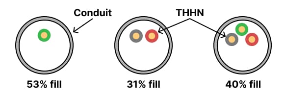
Diagram illustrating conduit fill percentages for 1, 2, and 3+ conductors based on NEC guidelines.
info
💡 Key Insight: The 40% fill rule for three or more conductors is most commonly used in electrical installations. This provides adequate space for heat dissipation and wire pulling while maximizing conduit utilization.
Conductor Area Calculation
Every conductor has a specific cross-sectional area including insulation. NEC Chapter 9 Table 5 lists these areas for common conductor types:
Calculation Formula:
40% Fill Rule:
NEC Conduit Fill Tables and Charts
Standard Conduit Sizes
Electrical conduit comes in standard trade sizes measured in inches:
Common Trade Sizes: ½", ¾", 1", 1¼", 1½", 2", 2½", 3", 3½", 4", 5", 6"
⚡ Working on similar calculations?
Get practical electrical tips and quick answers like this — straight to your inbox.
Maximum Wire Fill Chart - THHN/THWN Conductors
The following chart shows maximum number of THHN/THWN conductors (most common insulation type) at 40% fill:
| Wire Size (AWG) | ½" Conduit | ¾" Conduit | 1" Conduit | 1¼" Conduit | 1½" Conduit | 2" Conduit |
|---|---|---|---|---|---|---|
| 14 AWG | 9 | 16 | 26 | 43 | 58 | 96 |
| 12 AWG | 7 | 12 | 20 | 33 | 44 | 73 |
| 10 AWG | 5 | 9 | 15 | 25 | 34 | 56 |
| 8 AWG | 3 | 5 | 8 | 14 | 19 | 31 |
| 6 AWG | 1 | 4 | 6 | 10 | 14 | 23 |
| 4 AWG | 1 | 2 | 4 | 7 | 10 | 16 |
| 3 AWG | 1 | 1 | 3 | 6 | 8 | 14 |
| 2 AWG | 1 | 1 | 3 | 5 | 7 | 12 |
| 1 AWG | 0 | 1 | 1 | 4 | 5 | 9 |
| 1/0 AWG | 0 | 1 | 1 | 3 | 4 | 7 |
| 2/0 AWG | 0 | 1 | 1 | 2 | 3 | 6 |
| 3/0 AWG | 0 | 0 | 1 | 1 | 3 | 5 |
| 4/0 AWG | 0 | 0 | 1 | 1 | 2 | 4 |
EMT Conduit Internal Areas
Electrical Metallic Tubing (EMT) internal areas for fill calculations:
| Trade Size | Internal Diameter (inches) | 40% Fill Area (sq. in) | Total Area (100%) |
|---|---|---|---|
| ½" | 0.622 | 0.122 | 0.304 |
| ¾" | 0.824 | 0.213 | 0.533 |
| 1" | 1.049 | 0.346 | 0.864 |
| 1¼" | 1.380 | 0.598 | 1.496 |
| 1½" | 1.610 | 0.814 | 2.036 |
| 2" | 2.067 | 1.342 | 3.356 |
| 2½" | 2.731 | 2.343 | 5.858 |
| 3" | 3.356 | 3.538 | 8.846 |
| 3½" | 3.834 | 4.618 | 11.545 |
| 4" | 4.334 | 5.901 | 14.753 |
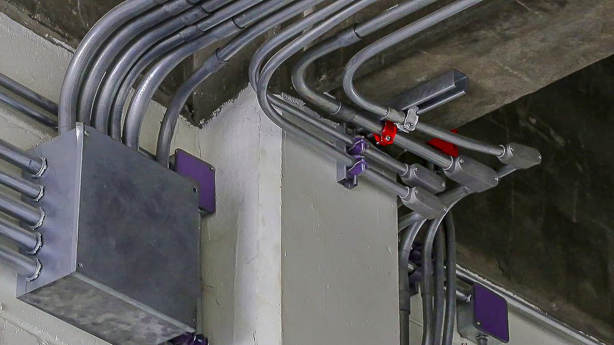
Example of electrical conduit installation showing THHN wires routed through EMT metallic conduits.
Photo by Sen NewsStep-by-Step Conduit Fill Calculations
Example 1 — Ten 12 AWG THHN Conductors (Single-Size Fill, With a Derating Flag)
Scenario: A lighting circuit homerun from a sub-panel to a junction box uses 10 conductors of 12 AWG THHN — five circuits sharing one conduit. Size the EMT conduit.
Step 1 — Individual conductor area (NEC Table 5)
12 AWG THHN = 0.0133 in²
Step 2 — Total conductor area
10 × 0.0133 = 0.133 in²
Step 3 — Try ½" EMT
40% fill capacity: 0.122 in² 0.133 > 0.122 → Fails. ½" EMT is not large enough.
This is the step most calculation errors happen — rounding 0.133 down and forcing it into ½" conduit. The margin is small but the code requirement is firm.
Step 4 — Try ¾" EMT
40% fill capacity: 0.213 in² 0.133 < 0.213 → Passes. The conductors occupy 62% of the allowable fill space.
Step 5 — Derating flag
Ten conductors in one conduit raises a derating question. If all ten are current-carrying (five hots and five neutrals, no equipment grounding conductors), NEC 310.15(C)(1) requires a 50% adjustment factor on conductor ampacity before you confirm wire size is adequate. That calculation is shown in full in Example 4 below.
Answer: ¾" EMT — pending derating verification if all ten conductors are current-carrying.
Example 2 — Sub-Panel Feeder With Oversized EGC (Mixed Wire Sizes)
Scenario: A 60A, 240V feeder runs from a main panel to a workshop sub-panel in EMT. The sub-panel serves both 240V equipment and 120V receptacles, so a neutral is required. Size the conduit.
Conductors:
- 2 × 6 AWG THHN (ungrounded — Line 1 and Line 2)
- 1 × 6 AWG THHN (grounded conductor / neutral)
- 1 × 10 AWG THHN (equipment grounding conductor)
The EGC size comes from NEC 250.122 Table: a 60A overcurrent device requires a minimum 10 AWG copper EGC. Using the same size as the phase conductors is conservative but wastes conduit space. 10 AWG is the correct minimum.
Step 1 — Conductor areas (NEC Table 5)
6 AWG THHN = 0.0507 in² 10 AWG THHN = 0.0211 in²
Step 2 — Total conductor area
Step 3 — Try ½" EMT
40% fill capacity: 0.122 in² 0.1732 > 0.122 → Fails.
Step 4 — Try ¾" EMT
40% fill capacity: 0.213 in² 0.1732 < 0.213 → Passes. Conductors use 81% of available fill.
Practical note on the 2-wire variation: If the sub-panel serves only 240V loads and no neutral is needed, the total becomes:
½" EMT capacity is 0.122 in². Difference: 0.0005 in² — the conductors are 0.4% over the limit. ½" EMT still fails, ¾" EMT is still the answer. In practice this comes up on small feeder circuits and it's a common miscalculation when the neutral is left out of the math without re-checking the conduit size.
Answer: ¾" EMT for both the 3-wire and 4-wire configurations.
Example 3 — Underground PVC for a 480V Motor Circuit
Scenario: A 25 HP, 480V, 3-phase pump motor is located outdoors 80 feet from the motor control center. The circuit runs underground in a direct-burial trench (not concrete-encased). Size the conduit and confirm conductor type.
Why not EMT underground: EMT is not listed for direct burial in NEC 358.10(B). Underground runs require PVC Schedule 40 (minimum), rigid PVC Schedule 80 if encased in concrete, or HDPE.
Conductor type: Underground and wet-location conductors must be rated for wet conditions. THWN-2 is suitable. THWN-2 has the same cross-sectional area as THHN for fill calculations.
Step 1 — Determine conductor size
Motor full-load current from NEC Table 430.250: 25 HP, 480V, 3-phase = 34A.
Minimum branch circuit conductor ampacity per NEC 430.22: 125% × 34A = 42.5A.
8 AWG THWN-2 (ampacity 50A at 75°C per NEC 310.16) satisfies this requirement.
EGC minimum per NEC 250.122: the branch circuit overcurrent device for this motor will be sized to at least 60A. Minimum EGC = 10 AWG copper.
Conductors:
- 3 × 8 AWG THWN-2 (phase)
- 1 × 10 AWG THWN-2 (EGC) Step 2 — Conductor areas
8 AWG THWN-2 = 0.0366 in² 10 AWG THWN-2 = 0.0211 in²
Step 3 — Total conductor area
Step 4 — Select PVC Schedule 40 conduit
Using the PVC Schedule 40 40% fill capacities from the table in the next section:
| Trade Size | 40% Fill Capacity | Result |
|---|---|---|
| ½" PVC Sch 40 | 0.114 in² | 0.1309 > 0.114 → Fails |
| ¾" PVC Sch 40 | 0.203 in² | 0.1309 < 0.203 → Passes |
If the trench is concrete-encased (NEC 352.10(F) requires Schedule 80):
¾" PVC Schedule 80 has a 40% fill capacity of 0.173 in². 0.1309 < 0.173 → Passes in ¾" Schedule 80 as well.
Answer: ¾" PVC Schedule 40 for direct burial; ¾" PVC Schedule 80 if concrete-encased.
Example 4 — Fill and Derating Together (Where 12 AWG Fails)
This example is the one most guides skip. Conduit fill and conductor derating are separate calculations, but the results interact: upsizing a conductor to satisfy derating can push the fill over the conduit's limit, forcing a larger conduit than the fill calculation alone would have required.
Scenario: A commercial office distribution panel homerun runs five 20A branch circuits in a single EMT conduit. Each circuit uses one hot, one neutral, and one ground, all 12 AWG THHN.
Conductors:
- 15 total: 5 hot + 5 neutral + 5 EGC
- Current-carrying conductors (CCCs): 10 (hots and neutrals — EGCs are excluded per NEC 310.15(E)(1)) Fill calculation with 12 AWG:
15 × 0.0133 = 0.1995 in²
| Trade Size | 40% Capacity | Result |
|---|---|---|
| ¾" EMT | 0.213 in² | 0.1995 < 0.213 → Passes (94% used) |
| 1" EMT | 0.346 in² | 0.1995 < 0.346 → Comfortable margin |
Fill-only result: ¾" EMT works, though the 94% fill makes pulling 15 conductors through ¾" conduit difficult. 1" EMT is the practical choice regardless. But derating changes the answer entirely.
Derating calculation:
10 CCCs in one conduit → NEC 310.15(C)(1) Table → 50% adjustment factor.
12 AWG THHN ampacity calculation:
- NEC 310.16, 90°C column: 30A base ampacity
- Apply 50% factor: 30A × 0.50 = 15A
- Terminal temperature check (most panelboard terminals are rated 75°C): 12 AWG at 75°C = 20A
- Since 15A < 20A, the terminal cap does not override — effective ampacity is 15A A 15A effective ampacity cannot protect a 20A circuit. 12 AWG fails. The wire size must be increased.
Solution — Upsize to 10 AWG THHN:
- NEC 310.16, 90°C column: 40A base ampacity
- Apply 50% factor: 40A × 0.50 = 20A
- Terminal check: 10 AWG at 75°C = 35A; since 20A < 35A, effective ampacity = 20A ✓
- 20A adequately protects the 20A circuit ✓ Recalculate fill with 10 AWG:
15 × 0.0211 = 0.3165 in²
| Trade Size | 40% Capacity | Result |
|---|---|---|
| ¾" EMT | 0.213 in² | 0.3165 > 0.213 → Fails |
| 1" EMT | 0.346 in² | 0.3165 < 0.346 → Passes |
The fill calculation that appeared to pass in ¾" EMT with 12 AWG now fails once the correct conductor size is determined through derating.
Final answer: 1" EMT with 10 AWG THHN throughout.
The practical takeaway: whenever a conduit carries more than six current-carrying conductors, run the derating check before locking in conduit size. The conductor upsize almost always forces a conduit upsize too.
PVC Conduit Fill Tables (NEC Table 4)
PVC is the standard choice for underground runs, concrete-encased raceways, and corrosive environments where EMT is not suitable. Schedule 40 is permitted in most above-grade and direct-burial applications. Schedule 80 is required where the conduit is subject to physical damage (NEC 352.10(F)) and for concrete-encased runs.
PVC has a slightly smaller bore than EMT for the same trade size, which means the same conductor bundle will sometimes require one size larger PVC conduit than EMT. The difference is small at ½" through 1" trade sizes but can matter at the margins.
PVC Schedule 40 — Internal Area and 40% Fill Capacity
| Trade Size | Internal Diameter (in) | Total Area (in²) | 40% Fill (in²) | 2-Conductor 31% (in²) | 1-Conductor 53% (in²) |
|---|---|---|---|---|---|
| ½" | 0.602 | 0.285 | 0.114 | 0.088 | 0.151 |
| ¾" | 0.804 | 0.508 | 0.203 | 0.157 | 0.269 |
| 1" | 1.029 | 0.832 | 0.333 | 0.258 | 0.441 |
| 1¼" | 1.360 | 1.453 | 0.581 | 0.450 | 0.770 |
| 1½" | 1.590 | 1.986 | 0.794 | 0.616 | 1.053 |
| 2" | 2.047 | 3.291 | 1.316 | 1.020 | 1.744 |
| 2½" | 2.445 | 4.695 | 1.878 | 1.455 | 2.488 |
| 3" | 3.042 | 7.268 | 2.907 | 2.253 | 3.852 |
| 4" | 3.998 | 12.554 | 5.022 | 3.892 | 6.654 |
Source: NEC Table 4, Chapter 9. Verify internal diameters against the edition you are citing — values were updated in the 2020 and 2023 cycles.
PVC Schedule 80 — Internal Area and 40% Fill Capacity
Schedule 80 has thicker walls than Schedule 40. For the same trade size, the bore is smaller, which reduces fill capacity. Use these values for all concrete-encased conduit calculations.
| Trade Size | Internal Diameter (in) | Total Area (in²) | 40% Fill (in²) |
|---|---|---|---|
| ½" | 0.546 | 0.234 | 0.094 |
| ¾" | 0.742 | 0.432 | 0.173 |
| 1" | 0.957 | 0.719 | 0.288 |
| 1¼" | 1.278 | 1.283 | 0.513 |
| 1½" | 1.500 | 1.767 | 0.707 |
| 2" | 1.939 | 2.953 | 1.181 |
| 2½" | 2.323 | 4.238 | 1.695 |
| 3" | 2.900 | 6.605 | 2.642 |
| 4" | 3.826 | 11.497 | 4.599 |
Rigid Metal Conduit (RMC) Fill Tables
RMC is required in several specific applications: service entrance conduit from the utility meter to the first disconnect, exposed outdoor runs subject to severe physical damage, and hazardous locations classified under NEC Articles 500–516. Its internal diameter is slightly larger than EMT for the same trade size, so conductor fill capacity is marginally higher — though the difference is rarely the deciding factor.
RMC — Internal Area and 40% Fill Capacity
| Trade Size | Internal Diameter (in) | Total Area (in²) | 40% Fill (in²) | 2-Conductor 31% (in²) | 1-Conductor 53% (in²) |
|---|---|---|---|---|---|
| ½" | 0.632 | 0.314 | 0.125 | 0.097 | 0.166 |
| ¾" | 0.836 | 0.549 | 0.220 | 0.170 | 0.291 |
| 1" | 1.063 | 0.887 | 0.355 | 0.275 | 0.470 |
| 1¼" | 1.394 | 1.526 | 0.610 | 0.473 | 0.809 |
| 1½" | 1.624 | 2.071 | 0.828 | 0.642 | 1.098 |
| 2" | 2.083 | 3.408 | 1.363 | 1.056 | 1.806 |
| 2½" | 2.489 | 4.866 | 1.946 | 1.508 | 2.579 |
| 3" | 3.090 | 7.499 | 3.000 | 2.325 | 3.975 |
| 4" | 4.090 | 13.135 | 5.254 | 4.072 | 6.962 |
Source: NEC Table 4, Chapter 9. Verify against current edition.
Intermediate Metal Conduit (IMC) has a larger bore than both EMT and RMC for most trade sizes, making it the highest-capacity metal raceway option. If space is constrained and you need to maximize conductor count, IMC is worth sizing before stepping up to the next trade size. IMC is listed for all the same applications as RMC under NEC 342.10.
VFD Output Wiring: Keep It in Its Own Conduit
Variable frequency drive output conductors — the run between the drive output terminals and the motor — should always be in a dedicated conduit, separate from all other circuits including the VFD input. This is not a NEC hard requirement in most cases, but it is the manufacturer requirement for virtually every major VFD brand, and violating it typically voids the warranty.
The reason is conducted and radiated electrical noise. VFD output waveforms are not sinusoidal — they are PWM-modulated switched voltages with high-frequency harmonic content. When VFD output conductors share conduit with control wiring or other power circuits, that harmonic energy couples inductively into adjacent conductors and causes nuisance trips, sensor errors, and premature insulation failure.
In practice, the conduit sizing for a VFD motor circuit is straightforward — typically three phase conductors plus a ground, sized per NEC 430.22 — but the routing decision matters more than it does for standard motor circuits. Keep the VFD output conduit:
- Separated from all signal and control wiring
- As short as practical (longer runs increase the capacitive coupling effect)
- Terminated at the motor terminal box without routing through a shared junction box
Some VFD manufacturers require shielded motor cable rather than standard THWN-2 in conduit for output runs over 50 feet. Check the drive installation manual for the specific distance threshold and cable specification before sizing the conduit. Shielded motor cable has a larger overall diameter than the same AWG THWN-2, which increases the fill calculation slightly.
Quick Reference Wire Fill Charts
Maximum Conductors for Common Applications
120V Branch Circuits (14 AWG + Ground)
| Conduit Size | 2-Wire + Ground | 3-Wire + Ground | 4-Wire + Ground |
|---|---|---|---|
| ½" | 3 circuits | 2 circuits | 1 circuit |
| ¾" | 5 circuits | 4 circuits | 3 circuits |
| 1" | 8 circuits | 6 circuits | 5 circuits |
240V Circuits (12 AWG + Ground)
| Conduit Size | Single 240V Circuit | Two 240V Circuits | Three 240V Circuits |
|---|---|---|---|
| ½" | ✓ (3 wires) | ✗ | ✗ |
| ¾" | ✓ (3 wires) | ✓ (6 wires) | ✗ |
| 1" | ✓ (3 wires) | ✓ (6 wires) | ✓ (9 wires) |
Derating Considerations
When more than three current-carrying conductors share a conduit, ampacity derating applies per NEC 310.15(C)(1):
| Current-Carrying Conductors | Ampacity Adjustment Factor |
|---|---|
| 4-6 | 80% |
| 7-9 | 70% |
| 10-20 | 50% |
| 21-30 | 45% |
| 31-40 | 40% |
| 41+ | 35% |
warning
⚠️ Important: Neutral conductors carrying unbalanced current and equipment grounding conductors count as current-carrying conductors for derating purposes. Always verify local code interpretations.
Common Conduit Sizing Applications
Residential Wiring
Typical ½" EMT Applications:
- Single 15A or 20A branch circuit
- Three 14 AWG conductors (2 hot + neutral or 1 hot + neutral + ground)
- Maximum distance: Consider voltage drop for long runs
Typical ¾" EMT Applications:
- Multiple branch circuits to panel
- Service entrance for small loads
- Feeder circuits up to 60A
Commercial Applications
Lighting Circuits: For commercial buildings with multiple lighting circuits:
- 1" conduit: Up to 8 circuits (14 AWG)
- 1¼" conduit: Up to 13 circuits (14 AWG)
- Consider smart lighting control wiring
Power Distribution: Office space power distribution typically uses:
- 1" to 1½" conduit for branch circuit homerun
- 2" to 3" conduit for sub-panel feeders
- Larger conduits for main distribution
Industrial Installations
Motor Circuits: Size based on motor full-load ampacity:
- Include oversized ground wire per NEC 250.122
- Consider VFD installations requiring additional conductors
- Account for control wiring in separate conduits
Control Wiring: PLC and instrumentation wiring:
- Typically 18-16 AWG
- May require separation from power circuits
- Consider shielded cable requirements
Best Practices and Code Compliance
Installation Best Practices
1. Wire Pulling Limits
- Maximum pull length without junction: 100 feet
- Use pull boxes for longer runs or multiple bends
- Limit total bends to 360° between boxes
2. Conduit Selection
- EMT: Indoor dry locations, easiest to work with
- Rigid PVC: Outdoor underground, corrosion resistance
- Rigid Metal: High-abuse areas, mechanical protection
- Flexible: Short connections to equipment
3. Future Expansion Consider oversizing conduit by one size for:
- Potential circuit additions
- Equipment upgrades
- Easier wire pulling
- Rule of thumb: Design for 60-70% fill rather than maximum 40%
Common Mistakes to Avoid
1. Forgetting Ground Conductors Always include equipment grounding conductors in fill calculations. This is a frequent oversight that causes code violations.
2. Mixing Conductor Types Use consistent insulation types (all THHN or all THWN-2). Mixing types complicates calculations and may violate temperature ratings.
3. Ignoring Ambient Temperature High-temperature locations require:
- Temperature rating adjustments
- Possible larger conduit for heat dissipation
- Special insulation types
4. Undersizing for Long Runs Account for:
- Voltage drop on long runs
- Difficulty pulling wire through small conduit
- Future troubleshooting and maintenance
Inspection and Compliance
Before Installation:
- Verify local amendments to NEC
- Obtain required permits
- Submit drawings for approval
- Confirm conduit type specifications
During Installation:
- Mark conduit contents at panels and boxes
- Document as-built conditions
- Use proper conduit supports per NEC Table 344.30(B)(2)
- Maintain minimum bending radius
After Installation:
- Test for shorts and grounds
- Verify proper grounding continuity
- Label circuits clearly
- Document in panel schedules
Conduit Fill Calculation Guide
Manual Calculation Steps
- Step 1: List all conductors including grounds
- Step 2: Find each conductor area from NEC Table 5
- Step 3: Sum total conductor area
- Step 4: Select conduit with 40% fill area ≥ total conductor area
- Step 5: Verify with NEC Annex C tables
Quick Sizing Rules of Thumb
For THHN/THWN Copper:
- ½" conduit: Up to 9 conductors of 14 AWG
- ¾" conduit: Up to 12 conductors of 12 AWG
- 1" conduit: Up to 15 conductors of 10 AWG
- Add one size: If near maximum or long pull
Advanced Considerations
Special Conductor Types
- Compact Conductors: Smaller cross-section, allow more per conduit
- High-Temperature Conductors: THHN vs THWN-2 ratings
- Armored Cable: Cannot mix with individual conductors in conduit
- Control Cable: Different fill rules for instrumentation
Underground Installations
PVC conduit for direct burial requires:
- Minimum burial depth per NEC 300.5
- Proper bedding and backfill
- Warning tape placement
- Larger size for thermal considerations
Parallel Conductors
For large loads requiring parallel conductors:
-
Equal lengths for current sharing
-
Same conduit size for each set
-
Separate grounding per NEC 250.122
-
Phase identification marking
Conclusion: Ensuring Safe and Compliant Conduit Installation
Proper conduit fill is fundamental to electrical safety, code compliance, and installation efficiency. By following NEC guidelines, using accurate calculations, and applying the charts and formulas in this guide, you can size conduits correctly for any application while maintaining code compliance and installation quality.
Key Takeaways:
- Always use the 40% fill rule for three or more conductors
- Include all conductors (power and ground) in calculations
- Select next size up when near maximum fill
- Consider future expansion in your design
- Verify calculations with NEC tables and local codes
Whether sizing conduit for simple residential circuits or complex industrial installations, the principles remain consistent. Proper planning, accurate calculations, and adherence to NEC requirements ensure safe, reliable, and code-compliant electrical systems.
For related electrical calculations and design guidance, explore our comprehensive resources on wire sizing, circuit breaker selection, and electrical safety practices.
🔗 Related Posts
- Wire Size Calculator: Complete Guide with Single Phase, 3-Phase & DC Calculations
- Circuit Breaker Sizing: Complete Guide with Wire Size Charts & NEC Code Requirements
- Complete Guide to Voltage Drop: Calculations, Tables & Calculators
- Difference Between Grounding and Earthing: Complete Guide
- Understanding Induction Motors: Working Principle, Calculations, and Applications
- MCB vs MCCB: Complete Comparison Guide with Selection Criteria, Ratings & Applications
- Wire Size for 50 Amp Breaker: Complete Guide with Charts, NEC Requirements & Installation Tips
- PVC Conduit Fill Chart for 10 AWG Wire: Complete NEC Guide with Capacity Tables
Helpful Calculators
- Ohm's Law Calculator
- Voltage Drop Calculator
- Power Factor Calculator
- Capacitor and Inductor Reactance Calculator
Credits
- Photo by Drew Beamer on Unsplash
⭐ Was this article helpful?
IDAR Mohamed
Electrical Engineer
Electrical Engineer specialized in power systems, electrical installations, and energy efficiency. Passionate about simplifying complex electrical concepts into practical guides. (University of applied sciences graduate, with experience in HV/LV systems and industrial installations.)
- Conduit Fill
- Electrical Conduit
- NEC Requirements
- Wire Fill Chart