
MCB vs MCCB: Complete Comparison Guide with Selection Criteria, Ratings & Applications
- Admin: IDAR Mohamed
- 22 Oct 2025
- 0
Choosing the right circuit breaker is critical for protecting your electrical systems from dangerous overcurrents and short circuits. The decision between MCB (Miniature Circuit Breaker) and MCCB (Molded Case Circuit Breaker) can significantly impact system safety, performance, and cost. Understanding the difference between MCB and MCCB is essential for electrical engineers, contractors, and facility managers making protection device selections.
Whether you're designing a residential electrical panel, specifying protection for industrial motors, or upgrading commercial power distribution systems, knowing when to use MCB vs MCCB ensures optimal protection while avoiding costly over-specification or dangerous under-protection.
This comprehensive guide covers everything you need to know about MCB and MCCB circuit breakers, including detailed comparisons, selection criteria, applications, and how they differ from RCCB and ACB protection devices.
Understanding Circuit Breaker Fundamentals
What is a Circuit Breaker?
A circuit breaker is an automatic electrical switch that protects electrical circuits and equipment from damage caused by:
- Overcurrent conditions: Excessive current flow beyond rated capacity
- Short circuits: Low-resistance paths causing massive current surges
- Ground faults: Unintended current paths to ground (in specialized breakers)
Unlike fuses that must be replaced after operation, circuit breakers can be reset and reused, making them more economical and practical for modern electrical installations.
Key Protection Functions
Circuit breakers provide essential protection through:
Thermal Protection:
- Bimetallic strip heats and bends under sustained overcurrent
- Trips breaker for overload conditions (1.05x to 1.4x rated current)
- Time-delayed response prevents nuisance tripping on startup currents
Magnetic Protection:
- Electromagnetic coil creates magnetic field proportional to current
- Instantly trips on short circuit conditions (typically 3x to 10x rated current)
- Fast response (milliseconds) prevents equipment damage and fire hazards
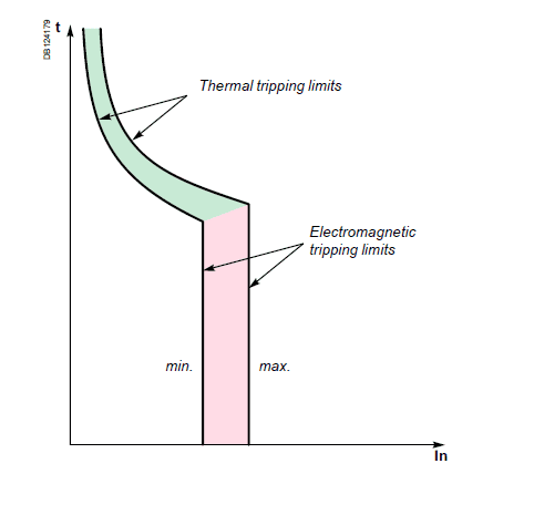
MCCB Protection Graph: Thermal overload protection and Magnetic short-circuit protection illustrated with trip response curves
Image by Schneider ElectricWhat is an MCB (Miniature Circuit Breaker)?
MCB Definition and Construction
A Miniature Circuit Breaker (MCB) is a compact, automatically operated electrical switch designed to protect low-voltage electrical circuits from overcurrent and short circuit conditions. The term "miniature" refers to its compact size compared to older, larger circuit protection devices.
MCB Technical Specifications
Current Ratings:
- Range: 0.5A to 125A (commonly up to 100A)
- Standard ratings: 6A, 10A, 16A, 20A, 25A, 32A, 40A, 50A, 63A, 80A, 100A
Breaking Capacity (Short Circuit Current):
- Type B: 3kA to 6kA (residential applications)
- Type C: 6kA to 10kA (commercial applications)
- Type D: 10kA to 25kA (industrial applications with high inrush currents)
Voltage Ratings:
- Single-phase: 230V AC (120V in North America)
- Three-phase: 400V AC (208V or 480V in North America)
Trip Characteristics:
| Type | Trip Range | Application |
|---|---|---|
| Type B | 3-5 x In | Residential, lighting, general purpose |
| Type C | 5-10 x In | Commercial, motors with moderate inrush |
| Type D | 10-20 x In | Industrial motors, transformers, high inrush loads |
| Type K | 8-12 x In | Motor protection, industrial equipment |

MCB Trip Characteristics Curves for Types B, C, and D showing typical trip ranges and applications
Image by Schneider ElectricWhere In = Nominal rated current
MCB Construction Features
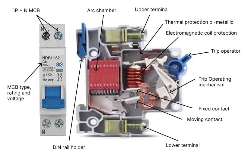
MCB Construction Features: Internal Components and Physical Design
Internal Components:
- Fixed bi-metallic strip: Thermal protection element
- Electromagnetic coil: Magnetic trip mechanism
- Arc chute: Extinguishes arc during interruption
- Contact mechanism: Silver-plated contacts for low resistance
- Trip indicator: Visual indication of tripped state
Physical Characteristics:
- Compact modular design (typically 18mm wide per pole)
- DIN rail mounting for easy installation
- Single, double, or triple pole configurations
- No adjustable settings (fixed trip characteristics)
What is an MCCB (Molded Case Circuit Breaker)?
MCCB Definition and Construction
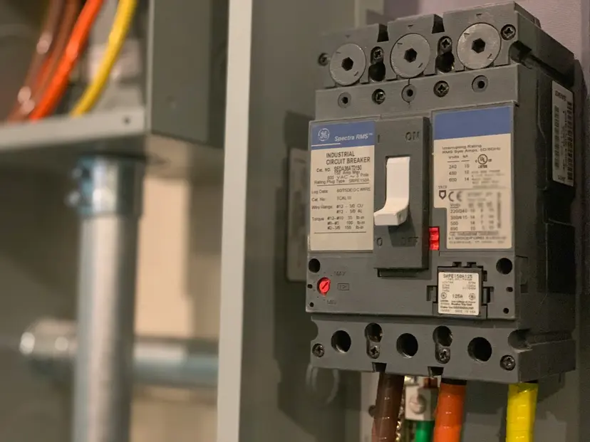
A Molded Case Circuit Breaker (MCCB) is a heavy-duty circuit protection device housed in a molded insulating case, designed for higher current ratings and industrial applications. MCCBs offer adjustable trip settings and higher breaking capacities compared to MCBs.
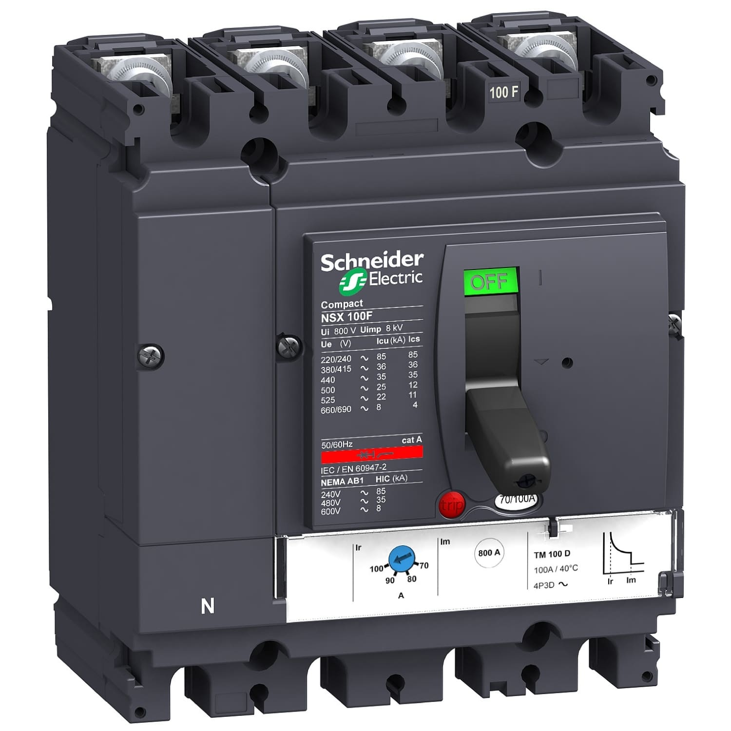
Molded Case Circuit Breaker (MCCB) for industrial applications with adjustable trip settings
Image by Schneider ElectricMCCB Technical Specifications
Current Ratings:
- Range: 10A to 2500A
- Common ratings: 16A, 25A, 32A, 50A, 63A, 100A, 160A, 250A, 400A, 630A, 800A, 1000A, 1600A
Breaking Capacity:
- Standard duty: 25kA to 50kA
- High breaking capacity: 50kA to 100kA
- Extra high: 100kA to 200kA (special applications)
Voltage Ratings:
- Low voltage: Up to 690V AC
- Common industrial: 415V AC three-phase
- DC ratings: Available for specific models (250V to 1000V DC)
MCCB Technical Specifications: Current ratings, breaking capacities, and voltage ratings for industrial applications
MCCB Advanced Features
Adjustable Trip Settings:
- Thermal adjustment: Fine-tune overload protection (typically 0.8x to 1x In)
- Magnetic adjustment: Adjust instantaneous trip level (typically 5x to 10x In)
- Time delay settings: Coordinate with downstream devices
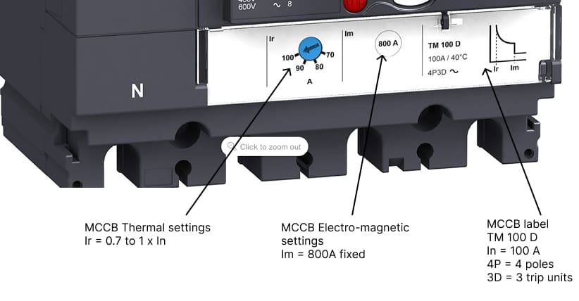
MCCB Adjustable Trip Settings: Thermal, Magnetic, and Time Delay adjustments for overload and short-circuit protection
Electronic Trip Units (Advanced MCCBs):
- Microprocessor-based protection
- LCD display for current monitoring
- Multiple protection functions (overload, short circuit, ground fault, undervoltage)
- Communication capabilities (Modbus, Profibus)
- Data logging and event recording
Protection Functions:
- L (Long-time): Overload protection with adjustable time-current curve
- S (Short-time): Short circuit protection with time delay
- I (Instantaneous): Ultra-fast short circuit protection
- G (Ground fault): Earth fault protection
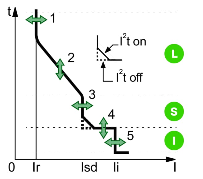
MCCB Tripping Curve: Long-time, Short-time, Instantaneous, and Ground fault protection functions illustrated
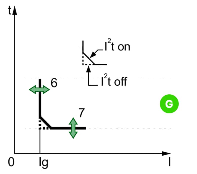
MCCB Tripping Curve: Ground fault protection functions illustrated
MCB vs MCCB: Detailed Comparison
Comprehensive Comparison Table
| Feature | MCB (Miniature Circuit Breaker) | MCCB (Molded Case Circuit Breaker) |
|---|---|---|
| Current Rating | 0.5A - 125A (typically up to 100A) | 10A - 2500A |
| Breaking Capacity | 3kA - 25kA | 25kA - 200kA |
| Trip Settings | Fixed (non-adjustable) | Adjustable (thermal and magnetic) |
| Physical Size | Compact, modular (18mm per pole) | Larger, bulky (varies by rating) |
| Applications | Residential, light commercial | Industrial, heavy commercial |
| Cost | Lower ($5 - $50) | Higher ($50 - $1000+) |
| Installation | DIN rail mounting, plug-in | Bolted connections, panel mounting |
| Remote Operation | Not typically available | Available with motorized mechanism |
| Maintenance | Replace entire unit | Can be serviced/repaired |
| Selectivity | Limited coordination | Excellent coordination capabilities |
| Protection Features | Basic thermal-magnetic | Advanced electronic options available |
| Response Time | Fixed characteristic curves | Adjustable time-current curves |
| Contact Status | Visual indicator only | Auxiliary contacts available |
| Cable Termination | Screw terminals (small cables) | Lug terminals (large cables up to 500mm²) |
| Standards | IEC 60898, UL 489 | IEC 60947-2, UL 489 |
Operating Principle Comparison
MCB Operating Mechanism:
- Normal operation: Current flows through thermal and magnetic elements
- Overload condition: Bi-metallic strip heats, bends, and mechanically trips contacts (5-30 seconds)
- Short circuit: Electromagnetic coil generates strong magnetic field, instantly trips (milliseconds)
- Arc extinction: Arc chute divides and cools arc for safe interruption
MCCB Operating Mechanism:
- Adjustable thermal element: Allows fine-tuning of overload protection
- Adjustable magnetic trip: Permits coordination with other protective devices
- Electronic trip units (advanced models): Microprocessor analyzes current patterns
- Enhanced arc extinction: Larger arc chutes handle higher fault currents
Performance Characteristics
MCB Advantages:
- Simple installation and replacement
- Cost-effective for low-current applications
- Consistent, reliable protection
- Compact design saves panel space
- Wide availability and standardization
MCB Limitations:
- Fixed trip characteristics limit flexibility
- Lower breaking capacity unsuitable for high fault current locations
- Limited to 100A maximum (typically)
- No remote monitoring or control
- Cannot coordinate as effectively with downstream devices
MCCB Advantages:
- High current ratings up to 2500A
- Adjustable settings optimize protection
- Superior breaking capacity (up to 200kA)
- Available with electronic trip units
- Excellent selectivity and coordination
- Remote operation capabilities
- Auxiliary contacts for monitoring
MCCB Limitations:
- Higher initial cost
- Larger physical size requires more space
- More complex installation
- May require professional calibration
- Overkill for simple residential applications
Selection Criteria: When to Use MCB vs MCCB
Application-Based Selection Guide
Use MCB When:
Residential Applications:
- House main distribution boards
- Individual circuit protection (lighting, outlets)
- Small appliance circuits (up to 100A)
- Cost is a primary consideration
- Simplicity is preferred
Light Commercial Applications:
- Small office buildings
- Retail stores (lighting and outlet circuits)
- Individual equipment protection under 100A
- Schools and educational facilities (standard circuits)
Specific Applications:
- ✓ Lighting circuits: 6A - 16A MCB Type B
- ✓ Power outlets: 16A - 32A MCB Type B/C
- ✓ Small air conditioners: 20A - 32A MCB Type C
- ✓ Water heaters: 32A - 40A MCB Type C
- ✓ Electric ovens: 32A - 50A MCB Type C
Use MCCB When:
Industrial Applications:
- Motor feeders over 100A
- Industrial machinery and equipment
- High fault current locations
- Selective coordination required
- Remote monitoring needed
Heavy Commercial Applications:
- Large commercial buildings (main and sub-distribution)
- Shopping malls and supermarkets
- Hotels and hospitals (critical loads)
- Data centers (precision protection)
- Manufacturing facilities
Specific Applications:
- ✓ Large motors: 100A - 800A MCCB with adjustable settings
- ✓ Generator protection: 400A - 1600A MCCB
- ✓ Main distribution: 630A - 2500A MCCB
- ✓ Industrial transformers: 250A - 1000A MCCB
- ✓ Busway protection: 400A - 1600A MCCB
Technical Selection Criteria
Step 1: Calculate Load Current
For motor loads:
Where:
- P = Motor power in kW
- V = Line voltage (typically 415V for three-phase)
- PF = Power factor (typically 0.85 for motors)
- η = Efficiency (typically 0.90)
Example: 50 kW motor at 415V
Breaker selection: Choose 100A MCCB (next standard size)
Step 2: Determine Breaking Capacity
Calculate available short circuit current at installation point:
Simplified method: Check utility-provided fault level or use short circuit calculation software.
Selection rule: Choose breaker with breaking capacity ≥ 1.25 × Available fault current
Example:
- Available fault current: 30 kA
- Required breaking capacity: 30 × 1.25 = 37.5 kA
- Selection: MCCB rated 50 kA or MCB rated 10 kA (if current rating permits)
Step 3: Coordination and Selectivity
For proper coordination:
- Upstream device (closer to source): Longer time delay, higher setting
- Downstream device (closer to load): Faster response, lower setting
Discrimination ratio: Upstream breaker rating should be ≥ 1.6 × downstream breaker rating
Example cascade:
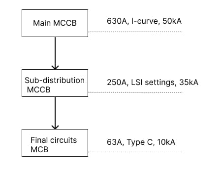
MCCB Distribution Hierarchy: Example cascade showing main, sub-distribution, and final protection levels
Cost Considerations
Initial Cost Comparison:
| Rating | MCB Cost | MCCB Cost | Cost Difference |
|---|---|---|---|
| 16A | $8 - $15 | $45 - $80 | 5-6x more |
| 32A | $12 - $25 | $60 - $100 | 4-5x more |
| 63A | $25 - $45 | $90 - $150 | 3-4x more |
| 100A | $40 - $80 | $120 - $250 | 2-3x more |
| 160A | N/A | $180 - $400 | - |
| 250A | N/A | $300 - $600 | - |
Note: Prices are indicative averages and vary by manufacturer, region, and specification.
Total Cost of Ownership:
- MCB: Lower initial cost, but must replace entire unit on failure
- MCCB: Higher initial cost, but can be serviced and calibrated
- Break-even point: Typically 3-5 years for industrial applications
MCB vs MCCB vs RCCB: Three-Way Comparison
Understanding RCCB (Residual Current Circuit Breaker)
RCCB Definition: A Residual Current Circuit Breaker (also called RCD - Residual Current Device) protects against electric shock by detecting earth leakage current and disconnecting the circuit.
Critical Differences
| Feature | MCB | MCCB | RCCB |
|---|---|---|---|
| Primary Protection | Overcurrent & short circuit | Overcurrent & short circuit | Earth leakage & electric shock |
| Thermal Protection | Yes | Yes | No |
| Magnetic Protection | Yes | Yes | No |
| Earth Fault Protection | No | Optional (with G-function) | Yes (primary function) |
| Operating Principle | Thermal-magnetic | Thermal-magnetic/Electronic | Current balance detection |
| Sensitivity | Amps (6A-125A) | Amps (10A-2500A) | Milliamps (10mA-300mA) |
| Trip Level | 1.13x - 1.45x In (thermal) | Adjustable | 30mA (typical for shock protection) |
| Response Time | Inverse time curve | Adjustable curve | <30ms for shock protection |
| Typical Rating | 6A - 100A | 10A - 2500A | 25A - 125A (current rating) |
| Cannot Protect Against | Earth leakage | Earth leakage (unless G-type) | Overload or short circuit |
Combined Protection Strategy
Complete Protection Requires:
For residential applications:

Main panel wiring hierarchy — RCCB 40A/30mA provides shock protection and feeds MCB 16A (lighting circuit), MCB 20A (kitchen outlets), and MCCB 63A 25kA (servers and UPS).
Coordination Strategy:
- ACB at main for highest breaking capacity and selectivity
- MCCB for distribution (adjustable settings ensure coordination)
- MCB for final circuits (cost-effective, adequate for application)
- Discrimination ratio maintained: ACB:MCCB ≥ 2:1, MCCB:MCB ≥ 1.6:1
Common Installation Mistakes and Solutions
Mistake 1: Using MCB in High Fault Current Locations
Problem: Installing 10kA MCB where available fault current is 15kA
Consequences:
- Breaker may fail to interrupt fault safely
- Potential for fire and equipment damage
- Breaker explosion risk
Solution:
- Calculate available fault current at installation point
- Use MCCB with adequate breaking capacity (25kA or higher)
- Verify with short circuit current calculations
Mistake 2: Incorrect MCB Type Selection for Motors
Problem: Using Type B MCB for motor starting (high inrush current)
Consequences:
- Nuisance tripping during motor start
- Reduced motor life due to repeated start attempts
- Productivity loss from unnecessary downtime
Solution:
- Use Type C or D MCB for motor circuits
- Calculate starting current (typically 5-8x full load)
- Consider soft starter or VFD to reduce inrush
Mistake 3: Oversizing Circuit Breakers
Problem: Using 50A MCCB for 20A load with 2.5mm² cable (rated 27A)
Consequences:
- Cable overheats before breaker trips
- Fire hazard from inadequate protection
- Violation of electrical codes
Solution:
- Match breaker rating to cable ampacity
- Follow wire sizing guidelines
- Breaker rating ≤ Cable ampacity
Mistake 4: Ignoring Selectivity Requirements
Problem: No coordination between upstream and downstream breakers
Consequences:
- Upstream breaker trips for downstream faults
- Unnecessary power loss to entire facility
- Difficult fault location and restoration
Solution:
- Use adjustable MCCB for upstream devices
- Maintain discrimination ratio (≥1.6:1)
- Use time-current curves to verify coordination
Mistake 5: Missing RCCB Protection Where Required
Problem: No RCCB on bathroom or outdoor outlet circuits
Consequences:
- Electric shock hazard
- Code violations
- Liability in case of accidents
Solution:
- Install 30mA RCCB for shock protection on:
- Bathroom circuits
- Outdoor outlets
- Kitchen countertop outlets
- Portable equipment circuits
Maintenance and Troubleshooting
MCB Maintenance Schedule
Monthly:
- Visual inspection for damage, discoloration
- Test operation (switch off and on)
- Check for unusual heat at terminals
Annually:
- Tighten all terminal connections
- Test with load (if possible)
- Check for corrosion or moisture
When to Replace MCB:
- After short circuit operation (some manufacturers recommend)
- Visible damage or burning marks
- Frequent nuisance tripping without cause
- Failed to trip during test
MCCB Maintenance Schedule
Monthly:
- Visual inspection of enclosure and indicators
- Check auxiliary contacts operation
- Verify trip unit display (electronic models)
Quarterly:
- Manual operation test (trip and close)
- Inspect for signs of overheating
- Check mechanical operation smoothness
Annually:
- Primary injection test (verify trip settings)
- Contact resistance measurement
- Insulation resistance test
- Calibration verification
3-5 Years:
- Complete overhaul by qualified technician
- Replace worn parts (contacts, springs)
- Update trip unit firmware (if applicable)
When to Overhaul MCCB:
- After major short circuit interruption
- High number of operations (check manufacturer specs)
- Contact erosion or pitting
- Inconsistent trip operation
Troubleshooting Common Issues
Problem: Breaker Trips Immediately After Reset
Possible Causes:
- Persistent short circuit in circuit
- Damaged cable insulation
- Faulty equipment on circuit
- Incorrect breaker rating
Diagnosis Steps:
- Disconnect all loads from circuit
- Test circuit with megohmmeter
- Reconnect loads one by one to identify fault
- Replace damaged components
Problem: Nuisance Tripping (Frequent Unexpected Trips)
Possible Causes:
- Overloaded circuit
- Incorrect breaker type (Type B on motor circuit)
- Loose connections causing arcing
- Harmonic currents (electronic loads)
- Aging breaker with reduced trip threshold
Solutions:
- Measure actual load current
- Upgrade to higher rated breaker with larger cable
- Change to appropriate breaker type
- Use harmonic-rated breaker or filter
- Replace aging breaker
Problem: Breaker Won't Trip During Fault
Possible Causes:
- Breaker mechanical failure
- Welded contacts
- Incorrect calibration (MCCB)
- Breaker exceeded breaking capacity
Immediate Action:
- Danger: Do not attempt to use circuit
- Disconnect at upstream breaker
- Replace faulty breaker immediately
- Investigate root cause of failure
Problem: Overheating at Breaker Terminals
Possible Causes:
- Loose connections
- Undersized breaker for load
- Poor quality connections or copper
- Corrosion at terminals
Solutions:
- Tighten connections to manufacturer torque specs
- Verify breaker rating adequate for load
- Clean and apply anti-oxidant compound
- Replace damaged terminals or lugs
Standards and Compliance
Key Compliance Requirements
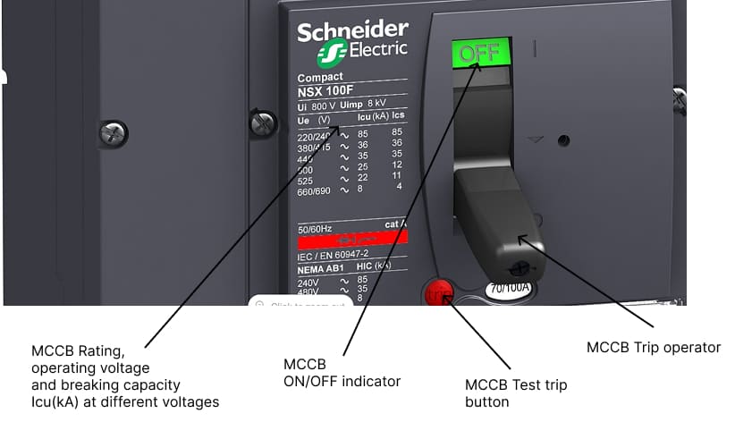
Marking Requirements: All breakers must be clearly marked with:
- Manufacturer name or trademark
- Current rating (In)
- Voltage rating
- Breaking capacity (Icn or Icu)
- Trip characteristic type (B, C, D)
- Standards compliance (IEC, UL)
Testing and Certification:
- Type tests by accredited laboratories
- Routine production tests
- Periodic verification testing
- Quality management system (ISO 9001)
Installation Requirements:
- Installed by qualified electrician
- Compliant with local electrical codes
- Proper torque applied to terminals
- Adequate ventilation and cooling
- Proper environmental protection (IP rating)
Advanced Topics
Electronic Trip Units in Modern MCCBs
Features and Benefits:
Protection Functions:
- LSIG Protection: Long-time, Short-time, Instantaneous, Ground fault
- Programmable curves: Customize protection to specific applications
- Zone selective interlocking: Coordinate with other electronic breakers
- Harmonic protection: Detect and protect against harmonic overload
Monitoring and Communication:
- Real-time current measurement (all three phases)
- Power quality monitoring (voltage, PF, harmonics)
- Energy metering and demand tracking
- Communication protocols: Modbus RTU, Profibus, Ethernet/IP
- Integration with SCADA and BMS systems
Advanced Features:
- Pre-alarm warnings before trip
- Load shedding capability
- Scheduled switching operations
- Data logging (fault history, load profile)
- Remote parameter adjustment
Selection Considerations:
- Initial cost: 2-3x standard thermal-magnetic MCCB
- Long-term value: Energy monitoring and predictive maintenance
- Best for: Critical loads, energy management, smart buildings
Selectivity and Discrimination
Types of Selectivity:
1. Total Selectivity (Current Discrimination): Upstream breaker never trips for faults in downstream zone
Requirement:
2. Partial Selectivity: Upstream breaker may trip for high-magnitude faults
Limit: Selective up to specific fault current level (e.g., 10kA)
3. Time Selectivity: Upstream breaker delays trip to allow downstream to clear fault
Requirement: Time delay difference ≥ 200-300ms
4. Zone Selective Interlocking (ZSI): Breakers communicate via wiring or bus
Benefit: Faster clearing while maintaining selectivity
Short Circuit Coordination Example
System Configuration:
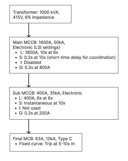
MCCB and MCB Coordination Hierarchy:
Transformer (1000 kVA, 415 V, 6% impedance) feeding main and sub-distribution breakers with defined long-time, short-time, and ground-fault protection settings.
Coordination Verification:
- Calculate fault current at each level
- Plot time-current curves
- Verify separation between curves (≥200ms)
- Confirm downstream breaker clears before upstream
- Check ground fault coordination
Environmental Considerations
Operating Environment Impact
Temperature Effects:
| Ambient Temperature | Effect on MCB/MCCB | Correction Factor |
|---|---|---|
| -25°C to 0°C | Increased trip threshold | 1.05 - 1.10 |
| 0°C to 40°C | Normal operation | 1.00 |
| 40°C to 50°C | Reduced trip threshold | 0.90 - 0.95 |
| 50°C to 70°C | Significantly reduced | 0.80 - 0.85 |
Solution for High Temperature:
- Derate breaker (use next size up)
- Improve ventilation in enclosure
- Use temperature-compensated electronic trip units
Altitude Effects: Above 2000m altitude:
- Reduced dielectric strength of air
- Derate breaking capacity by 10% per 1000m
- Use breakers specifically rated for altitude
Humidity and Corrosion:
- Use higher IP rating (IP54 or IP65 for harsh environments)
- Apply anti-corrosion coating
- Regular maintenance and inspection
IP (Ingress Protection) Ratings
| IP Rating | Protection Level | Application |
|---|---|---|
| IP20 | Finger protection, indoor | Standard distribution boards |
| IP40 | Small object protection | Industrial panels |
| IP54 | Dust protected, splash water | Outdoor enclosures |
| IP65 | Dust tight, water jet | Harsh environments |
| IP67 | Dust tight, temporary immersion | Marine, underwater applications |
Future Trends in Circuit Protection
Smart Circuit Breakers
IoT-Enabled Features:
- Cloud-based monitoring and analytics
- Predictive maintenance algorithms
- Remote control via smartphone app
- Integration with smart home systems
- Energy usage optimization
Market Direction:
- MCBs with basic communication (2025+)
- AI-powered fault prediction
- Self-diagnostic capabilities
- Cyber-security features
- Integration with renewable energy systems
Solid-State Circuit Breakers
Advantages:
- Ultra-fast operation (microseconds)
- No mechanical wear
- Silent operation
- Compact design
Current Limitations:
- Higher cost
- Heat dissipation challenges
- Limited to specific applications
Future Outlook:
- Gradual replacement of traditional breakers
- Starting with DC applications and data centers
- Mass adoption expected 2030-2035
Conclusion: Making the Right Choice
Selecting between MCB and MCCB requires careful consideration of multiple factors including current rating, breaking capacity, cost, application requirements, and future needs. Understanding the difference between MCB and MCCB ensures you choose the right protection device for safe, reliable, and cost-effective electrical installations.
Key Decision Points:
Choose MCB for:
- Residential and light commercial applications
- Current ratings up to 100A
- Fixed, simple protection requirements
- Cost-sensitive projects
- Standard breaking capacity needs (≤25kA)
Choose MCCB for:
- Industrial and heavy commercial applications
- Current ratings above 100A
- Adjustable protection settings needed
- High breaking capacity requirements (>25kA)
- Coordination with other protective devices essential
- Monitoring and communication required
Don't Forget RCCB:
- Always add 30mA RCCB for shock protection on accessible outlets
- Use in combination with MCB/MCCB (not as replacement)
- Essential for wet locations, outdoor circuits, and personal protection
For Very Large Applications:
- Consider ACB for currents above 2500A
- Evaluate total cost of ownership
- Factor in maintenance and serviceability needs
Whether you're protecting a simple residential circuit with an MCB or safeguarding industrial equipment with a sophisticated MCCB, proper selection and installation ensure electrical safety and system reliability. For complex installations, always consult with qualified electrical engineers and follow local electrical codes.
Ready to design your electrical protection system? Explore our comprehensive guides on circuit breaker sizing, power distribution panels, and short circuit analysis to ensure your installations meet all safety and performance requirements.
🔗 Related Posts
- Circuit Breaker Sizing: Complete Guide with Wire Size Charts & NEC Code Requirements
- Power Distribution Panel: Complete Guide to Electrical Distribution Boards
- Short Circuit Current Calculation: Complete Guide with Fault Analysis
- Variable Frequency Drive (VFD): Complete Guide to Motor Control
- Contactor vs Relay: Complete Comparison Guide
Helpful Calculators
- Ohm's Law Calculator
- Voltage Drop Calculator
- Power Factor Calculator
- Capacitor and Inductor Reactance Calculator
Credits
- Photo by Toolmash Expo on Unsplash
⭐ Was this article helpful?
IDAR Mohamed
Electrical Engineer
Electrical Engineer specialized in power systems, electrical installations, and energy efficiency. Passionate about simplifying complex electrical concepts into practical guides. (University of applied sciences graduate, with experience in HV/LV systems and industrial installations.)
- MCB vs MCCB
- Circuit Breakers
- Electrical Protection
- Short Circuit Protection
- MCCB vs ACB