

Difference Between Contactor and Relay: Complete Guide with Applications & Selection Criteria
- Admin: IDAR Mohamed
- 25 Sep 2025
- 0
Understanding the difference between contactors and relays is crucial for electrical engineers, technicians, and anyone working with industrial control systems. While both devices serve as electromagnetic switches in electrical circuits, they have distinct characteristics, applications, and design features that make them suitable for different purposes.
This comprehensive guide will clarify when to use contactors versus relays, their key differences, and practical applications to help you make informed decisions in your electrical projects and system designs.
What is a Contactor? Understanding High-Power Switching
A contactor is a heavy-duty electromagnetic switch designed specifically for switching high-power electrical loads, particularly in motor control applications. Contactors are built to handle significant electrical currents and voltages while providing reliable operation under demanding industrial conditions.
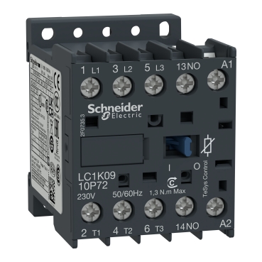 TeSys K miniature contactors and overload relays are available in 3 contactor ratings for the USA market for inductive motor applications up to 12 full-load amps and resistive loads up to 20 amps.
Key Characteristics of Contactors
Physical Construction:
- Larger and more robust than relays
- Heavy-duty contacts capable of handling high currents
- Strong electromagnetic coil system
- Designed for frequent operation (millions of cycles)
- Often includes arc suppression features
Electrical Specifications:
- Current ratings: Typically 10A to 1000A+
- Voltage ratings: Up to 690V AC for power circuits
- Coil voltages: 24V, 110V, 230V, 400V (AC/DC)
- Contact configurations: Usually 3-pole or 4-pole for three-phase systems
Operational Features:
- Built for continuous duty applications
- High mechanical and electrical endurance
- Capable of breaking high inductive loads
- Often includes auxiliary contacts for control circuits
Primary Applications of Contactors
Contactors excel in applications requiring high-power switching:
-
Three-Phase Motor Control
- Starting and stopping industrial motors
- Reversing motor rotation
- Star-delta motor starting systems
-
Lighting Control Systems
- High-power lighting circuits
- Street lighting control
- Stadium and arena lighting
-
Heating Element Control
- Industrial heating systems
- Electric furnaces
- HVAC system control
-
Power Distribution
- Load switching in distribution panels
- Generator transfer switching
- Power factor correction systems
What is a Relay? Understanding Control Circuit Switching
A relay is a smaller electromagnetic switch designed primarily for control circuits and low-power switching applications. Relays provide electrical isolation between control and switched circuits while enabling remote control of electrical devices.
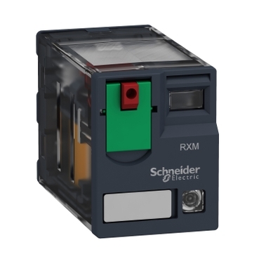 RXM miniature relays are part of Harmony Electromechanical Relays. This is a plug in relay to be mounted on a RXZE socket. It is a 2 C/O relay with current rating of 12A, control circuit voltage of 120 V AC 50/60 Hz.
Key Characteristics of Relays
Physical Construction:
- Compact and lightweight design
- Precision-engineered contacts for reliable switching
- Sensitive electromagnetic coil system
- Available in various mounting configurations
- Often transparent housing for visual inspection
Electrical Specifications:
- Current ratings: Typically 1A to 30A
- Voltage ratings: Various, depending on application
- Coil voltages: 5V, 12V, 24V, 110V, 230V (AC/DC)
- Contact configurations: SPST, SPDT, DPDT, multiple pole arrangements
Operational Features:
- Fast switching response
- Low coil power consumption
- High sensitivity to control signals
- Excellent electrical isolation
- Available in latching and non-latching types
Primary Applications of Relays
Relays are ideal for control and switching applications:
-
Control Circuit Logic
- Interlocking systems
- Sequence control
- Safety circuits
- Status indication
-
Signal Switching
- Communication systems
- Audio/video switching
- Instrumentation circuits
- Data acquisition systems
-
Automotive Applications
- Horn circuits
- Lighting control
- Fuel pump control
- Air conditioning systems
-
Home Automation
- Smart home systems
- Security systems
- HVAC control
- Appliance control
Comprehensive Comparison: Contactor vs Relay
Power Handling Capacity
| Aspect | Contactor | Relay |
|---|---|---|
| Current Rating | 10A - 1000A+ | 1A - 30A (typical) |
| Voltage Rating | Up to 690V AC | Varies by application |
| Power Application | High-power loads | Low-power control |
| Load Type | Motors, heating, lighting | Control circuits, signals |
Physical and Design Differences
Size and Weight:
- Contactors: Large, heavy-duty construction (often 4-12 inches)
- Relays: Compact design (typically 1-3 inches)
Contact System:
- Contactors: Heavy silver alloy contacts, multiple poles
- Relays: Precision contacts, various configurations
Mounting:
- Contactors: DIN rail, panel mounting, dedicated enclosures
- Relays: PCB, socket, DIN rail mounting
Operational Characteristics
Switching Speed:
- Contactors: Slower operation (50-100ms typical)
- Relays: Faster switching (5-20ms typical)
Coil Power Consumption:
- Contactors: Higher consumption (5-20VA)
- Relays: Lower consumption (0.5-5VA)
Operating Life:
- Contactors: Millions of mechanical operations
- Relays: Hundreds of thousands to millions of operations
Cost Considerations
Initial Cost:
- Contactors: Higher cost ($50-$500+)
- Relays: Lower cost ($5-$100)
Installation Cost:
- Contactors: Require larger enclosures and wiring
- Relays: Minimal space requirements
Maintenance:
- Contactors: Periodic inspection and contact replacement
- Relays: Generally replace entire unit when failed
Practical Wiring Examples and Applications
Example 1: Motor Control System
In a typical three-phase motor control system:
Contactor Application:
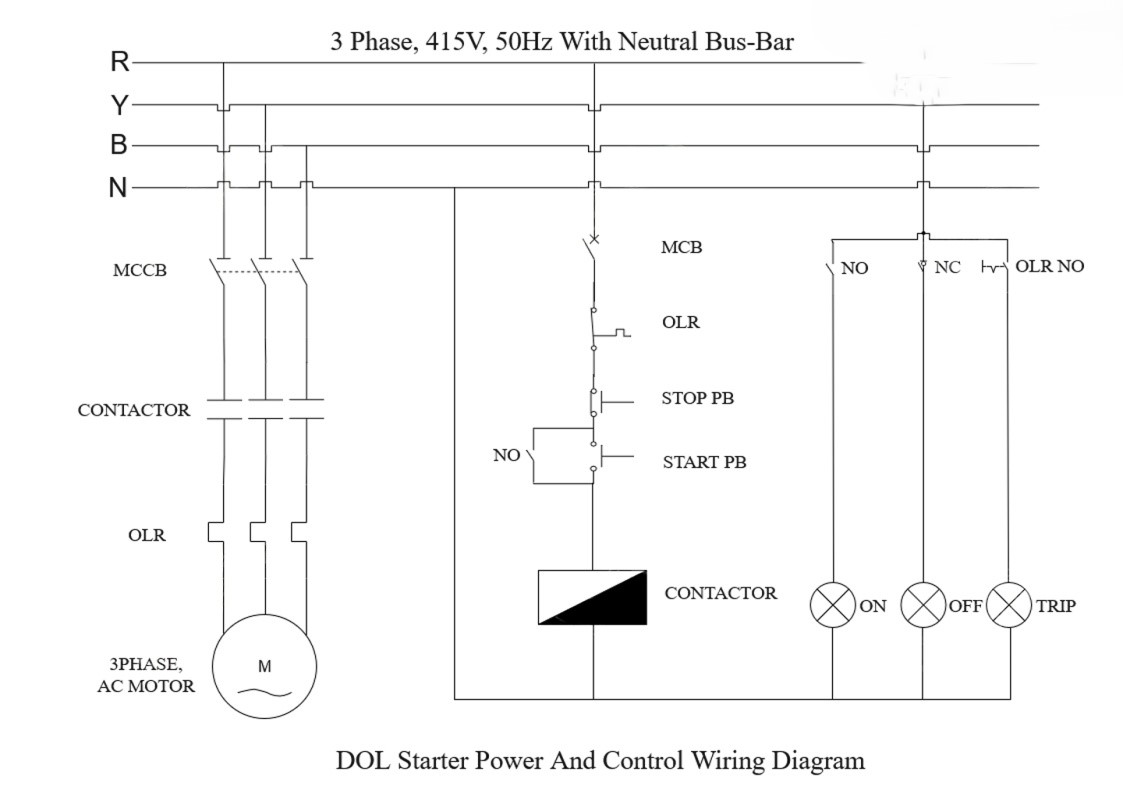
Relay Applications in the Same System:
- Control relay: Handles start/stop logic
- Auxiliary relay: Provides status feedback
- Safety relay: Implements emergency stop function
- Timer relay: Controls operational sequences
Example 2: Industrial Lighting Control
High-Power Circuit (Contactor):
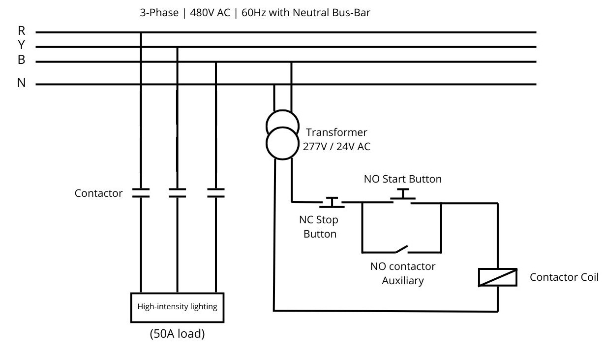 Note: Protection circuit breakers are not shown in the power and control circuits. They must be added in an actual implementation.
Control Circuit (Relay):
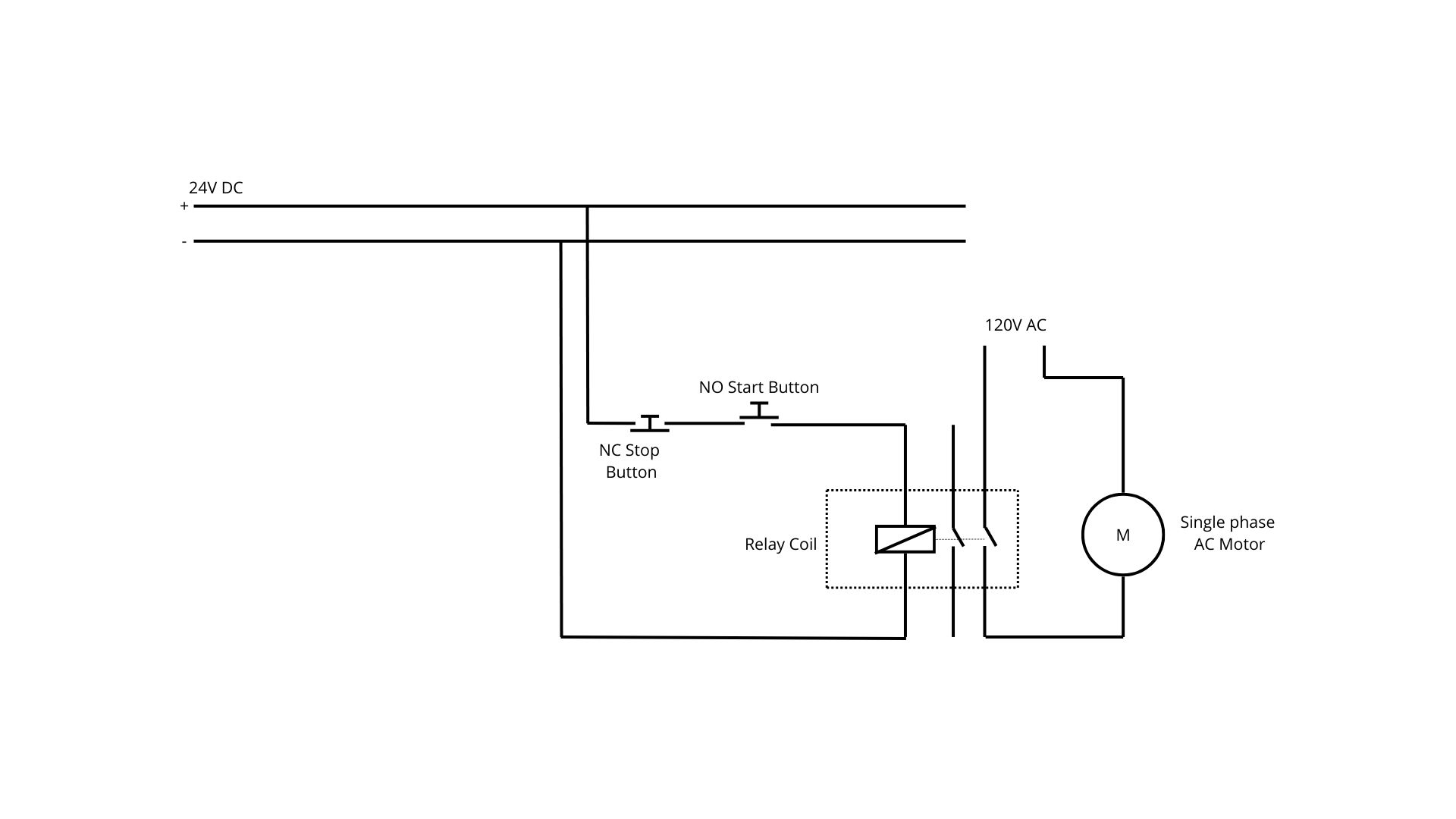 Note: This circuit diagram is provided only to illustrate relay applications in control circuits. It is not intended for real-world implementation.
Example 3: HVAC System Integration
Contactor Usage:
- Compressor motor switching (high current)
- Fan motor control (medium current)
- Heating element control (high current)
Relay Usage:
- Thermostat control logic
- Defrost cycle control
- Safety interlocks
- Status indication
Selection Criteria: When to Use Each Device
Choose a Contactor When:
-
High Current Requirements
- Load current exceeds 10A
- Three-phase motor applications
- High-power lighting or heating
-
Frequent Switching
- Applications requiring millions of operations
- Continuous duty cycles
- Industrial automation systems
-
Harsh Environmental Conditions
- High temperature applications
- Dusty or corrosive environments
- Outdoor installations
-
Safety and Code Requirements
- Motor control centers
- Industrial machinery
- Code-mandated disconnect requirements
Choose a Relay When:
-
Control Circuit Applications
- Logic control functions
- Signal switching
- Interface between control systems
-
Low Power Requirements
- Load current under 10A
- Control voltage switching
- Instrumentation circuits
-
Space Constraints
- Control panels with limited space
- PCB-mounted applications
- Distributed control systems
-
Cost-Sensitive Applications
- Budget constraints
- High-volume applications
- Simple on/off control
Advanced Applications and Integration
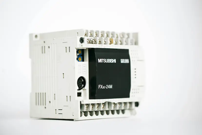
PLC Integration
Contactor Integration:
- Output modules control contactor coils
- Status feedback through auxiliary contacts
- Integration with motor protection systems
Relay Integration:
- Input/output signal conditioning
- Interface with sensors and actuators
- Logic expansion for complex control
Smart Systems and IoT
Modern Contactors:
- Smart contactors with integrated communication
- Condition monitoring capabilities
- Predictive maintenance features
Intelligent Relays:
- Programmable relay functions
- Communication protocols (Modbus, Ethernet)
- Data logging capabilities
Safety Systems Integration
Safety Contactors:
- Force-guided contacts for safety applications
- Redundant contact systems
- Integration with safety PLCs
Safety Relays:
- Safety-rated relay modules
- Emergency stop circuit integration
- Light curtain and guard door interfaces
Troubleshooting Common Issues
Contactor Problems and Solutions
Contact Welding:
- Cause: Excessive inrush current or improper sizing
- Solution: Use appropriate arc suppression, check load calculations
Coil Burnout:
- Cause: Overvoltage, undervoltage, or continuous duty exceeding rating
- Solution: Verify supply voltage, check coil specifications
Mechanical Wear:
- Cause: Excessive operating frequency or misalignment
- Solution: Regular maintenance, proper installation
Relay Problems and Solutions
Contact Oxidation:
- Cause: Low current switching or contamination
- Solution: Use appropriate contact materials, sealed relays
Coil Failure:
- Cause: Voltage spikes, moisture, or thermal stress
- Solution: Use suppression circuits, proper environmental protection
False Switching:
- Cause: Electrical noise or magnetic interference
- Solution: Proper shielding, filter circuits
Maintenance and Lifecycle Management
Contactor Maintenance
Regular Inspection:
- Visual inspection of contacts and arc chambers
- Tightening of terminal connections
- Cleaning of dust and debris
Preventive Maintenance:
- Contact replacement schedule
- Coil resistance testing
- Mechanical operation verification
Performance Monitoring:
- Current monitoring systems
- Temperature monitoring
- Vibration analysis
Relay Maintenance
Routine Checks:
- Contact resistance measurement
- Coil current verification
- Switching time measurement
Replacement Strategies:
- Scheduled replacement based on cycles
- Condition-based replacement
- System reliability requirements
Economic Considerations and ROI
Total Cost of Ownership
Contactor Economics:
- Higher initial cost but longer service life
- Lower cost per operation for high-frequency applications
- Reduced maintenance costs for appropriate applications
Relay Economics:
- Lower initial cost for control applications
- Higher replacement frequency in some applications
- Excellent value for low-power switching
Energy Efficiency
Power Consumption Comparison:
- Contactor coils: Typically 10-50W during operation
- Relay coils: Typically 1-10W during operation
System Efficiency:
- Proper device selection improves overall system efficiency
- Reduced energy waste through appropriate sizing
- Improved power factor in motor control applications
Practical Sizing Calculations and Examples
Example 1: Motor Starter Sizing with Overload Protection
Let's calculate the proper contactor and overload relay sizing for a 15 HP, 460V, three-phase induction motor.
Step 1: Determine Motor Full Load Current (FLC)
From NEC Table 430.250, the FLC for a 15 HP, 460V motor is 21 amperes.
Step 2: Contactor Sizing Calculation
Formula: Contactor Rating ≥ 1.25 × Motor FLC (for continuous duty)
Selection: Choose a 30A contactor (next standard size up)
AC-3 Rating Verification: For motor switching applications, verify the AC-3 rating at operating voltage:
- Selected contactor: 32A AC-3 rating at 480V ✓
Step 3: Overload Relay (OL) Sizing
- Service Factor ≥ 1.15: OL setting = 1.25 × FLC
- Service Factor < 1.15: OL setting = 1.15 × FLC
Assuming SF = 1.15:
Selection: Choose thermal overload relay with adjustment range 20-32A, set at 25A.
Step 4: Short Circuit Protection
Using inverse time circuit breaker:
Selection: Choose 60A circuit breaker (next standard size).
Complete Motor Starter Specification:
- Contactor: 30A, 3-pole, 480V coil
- Overload Relay: 20-32A adjustable, set at 25A
- Circuit Breaker: 60A, 3-pole
- Control Transformer: 480V/120V, 100VA
Example 2: Lighting Contactor Sizing with Time Delay
Calculate sizing for a commercial lighting system with 40 fluorescent fixtures, each drawing 2.5A at 277V.
Step 1: Calculate Total Load Current
Step 2: Contactor Sizing for Lighting Loads
For tungsten and fluorescent lighting, apply 125% factor:
Inrush Current Consideration: Fluorescent ballasts have 3-5× inrush:
Selection: Choose 125A contactor with AC-1 rating of 150A for resistive loads.
Step 3: Time Delay Relay Configuration
To prevent simultaneous switching of all fixtures:
Time Delay Calculation:
- Bank 1 (20 fixtures): Immediate start
- Bank 2 (20 fixtures): 2-second delay
Relay Configuration:
- Main contactor: 125A
- Time delay relay: 0.1-10 second adjustable
- Auxiliary contactor: 60A for delayed bank
Complete Lighting Control Specification:
- Main Contactor: 125A, 2-pole, 120V coil
- Auxiliary Contactor: 60A, 2-pole, 120V coil
- Time Delay Relay: ON-delay, 0.1-10s adjustable
- Control Circuit: 120V with photocell and time clock
Overload Protection Coordination Example
Motor: 25 HP, 480V, 3-phase, FLC = 32A
Step 1: Overload Relay Sizing
Step 2: Short Circuit Protection Coordination
Using fuses for better coordination:
Selection: 60A Class CC fuses
Step 3: Coordination Verification
Time-current coordination ensures:
- Overload relay trips at 125% × 32A = 40A in 20 seconds
- Fuse allows motor starting (6 × FLC for 10 seconds)
- Fuse clears fault currents above 500A in 0.1 seconds
Protection Cascade:
- Normal Overload: OL relay operates (20 seconds at 40A)
- High Overload: Fuse operates (2 seconds at 200A)
- Short Circuit: Fuse operates (0.01 seconds at 5000A)
Conclusion: Making the Right Choice
Understanding the difference between contactors and relays is essential for designing efficient, reliable electrical systems. The key is matching the device characteristics to your application requirements:
- Use contactors for high-power switching applications where robust construction and high current handling are essential
- Use relays for control circuits, signal switching, and applications where sensitivity, speed, and space efficiency are important
Both devices play crucial roles in modern electrical systems, often working together in integrated control solutions. Contactors handle the heavy lifting of power switching, while relays provide the intelligent control logic that makes systems safe, efficient, and automated.
The evolution toward smart, connected devices means that both contactors and relays are becoming more sophisticated, but their fundamental roles in electrical systems remain unchanged. By understanding their differences and applications, you can design better systems that are more reliable, efficient, and cost-effective.
Whether you're working on motor control systems, industrial automation, or building automation projects, the proper selection and application of contactors and relays will ensure your systems operate reliably for years to come.
🔗 Related Posts
- Variable Frequency Drive (VFD): Complete Guide
- Understanding Induction Motors: Working Principle and Applications
- Motor Voltage Drop Effects: Why Motors Fail
- Power Factor Correction: Save Energy and Cut Costs
Helpful Calculators
Credits
- Photo by ThisisEngineering RAEng on Unsplash
⭐ Was this article helpful?
IDAR Mohamed
Electrical Engineer
Electrical Engineer specialized in power systems, electrical installations, and energy efficiency. Passionate about simplifying complex electrical concepts into practical guides. (University of applied sciences graduate, with experience in HV/LV systems and industrial installations.)
- Contactor vs Relay
- Electrical Contactors
- Control Relays
- Motor Control