
High Pass Filter: Complete Guide with RC Circuits, Frequency Response & Calculations
- Admin: IDAR Mohamed
- 16 Oct 2025
- 0
High pass filters are essential components in modern electronics and signal processing, yet many engineers and technicians misunderstand how they work. Whether you're designing audio equipment, building instrumentation circuits, or working with AC signal coupling, understanding high pass filter theory and practical design is critical for achieving reliable results.
A high pass filter serves one fundamental purpose: it allows high-frequency signals to pass through while blocking or attenuating low-frequency signals. This simple concept has profound applications across virtually every field of electrical engineering, from audio processing to biomedical instrumentation. The RC high pass filter—constructed with just a resistor and capacitor—represents the foundation of filter design and provides valuable insights into frequency-dependent circuit behavior.
Table of Contents
- Understanding High Pass Filters: Fundamentals
- How High Pass Filters Work
- RC High Pass Filter Circuits
- Frequency Response and Cutoff Frequency
- High Pass Filter Design Calculations
- Practical Applications
- High Pass Filter vs Low Pass Filter
- Advanced Filter Design
Understanding High Pass Filters: Fundamentals
What is a High Pass Filter?
A high pass filter is a frequency-selective circuit that exhibits the following characteristics:
Key Characteristics:
- Passes high frequencies: Signals above the cutoff frequency pass through with minimal attenuation
- Blocks low frequencies: Signals below the cutoff frequency are significantly attenuated
- Frequency dependent: Output amplitude changes with input frequency
- Phase shifting: The filter introduces frequency-dependent phase shifts
The Cutoff Frequency Concept
The cutoff frequency (also called corner frequency or -3dB frequency) is the frequency where the filter transitions between passband and stopband regions. At this frequency, the output power equals half the input power, or equivalently, the output voltage is 70.7% () of the input voltage.
We can see why this is the case with a simple calculation. Power in a resistor is proportional to the square of the voltage:
At the cutoff frequency , the output power is half the input power :
Substitute :
Take the square root:
So at the cutoff frequency, the output voltage is about 70.7% of the input voltage.
Why Frequency Selectivity Matters
Real-world signals contain multiple frequency components, often with unwanted interference or noise at different frequencies. A high pass filter allows you to:
- Remove unwanted low-frequency content (rumble, hum, offset)
- Isolate desired high-frequency signals (audio content, sensor data)
- Protect circuits from DC and very low frequency interference
- Improve signal quality by eliminating noise outside the frequency band of interest
How High Pass Filters Work
Capacitive Reactance: The Key Principle
The foundation of high pass filter operation is capacitive reactance—the opposition a capacitor presents to AC signals at different frequencies.
Capacitive reactance is calculated as:
Where:
- = Capacitive reactance (ohms)
- = Frequency (Hz)
- = Capacitance (farads)
Critical Insight: As frequency increases, capacitive reactance decreases. This is why capacitors effectively pass high-frequency signals and block low-frequency signals.
Frequency-Dependent Behavior
At Very Low Frequencies
- Capacitive reactance is very high (approaching infinite resistance)
- The capacitor blocks most current flow
- The output voltage is severely attenuated
- Phase shift approaches -90° (capacitor dominates)
At the Cutoff Frequency
- Capacitive reactance equals the resistance value
- Output voltage is 70.7% of input voltage (-3dB)
- Phase shift equals -45°
- This is where the filter "turns on"
At High Frequencies
- Capacitive reactance becomes negligible
- The capacitor acts like a short circuit to AC signals
- Most signal passes through with minimal attenuation
- Phase shift approaches 0° (resistor path dominates)
Impedance and Signal Routing
In a simple RC high pass filter:
- Low frequencies: High capacitive reactance forces current through both R and C in series—voltage drops mostly across the capacitor, little reaches the output
- High frequencies: Low capacitive reactance means current bypasses the capacitor's opposing effect—signal passes to output with minimal loss
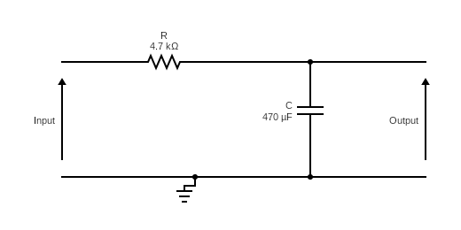
RC High Pass Filter Circuits
The Basic First-Order RC High Pass Filter
The simplest high pass filter configuration consists of a series capacitor followed by a parallel resistor:
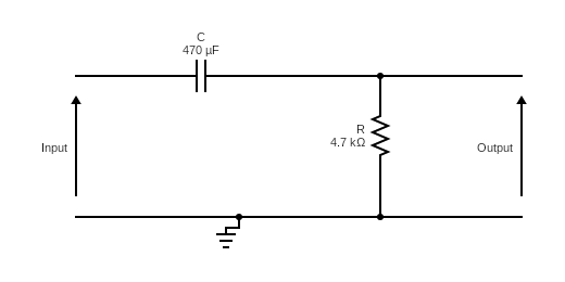
Circuit Analysis: Voltage Divider Approach
The RC high pass filter operates as a frequency-dependent voltage divider. The transfer function defines how output voltage relates to input voltage:
This can be rewritten in terms of magnitude and phase:
Where is the cutoff frequency.
Component Selection Guidelines
When designing an RC high pass filter, follow these guidelines:
| Consideration | Guideline | Why |
|---|---|---|
| Resistance Value | 1 kΩ - 1 MΩ typical | Balances impedance and practical component values |
| Capacitance Value | 1 nF - 1 µF typical | Achieves desired cutoff frequency |
| Output Loading | Load impedance > 10 × R | Minimizes loading effects and frequency distortion |
| Component Tolerance | 5-10% tolerance | Provides stable cutoff frequency |
| Temperature Stability | Use film capacitors | Better frequency stability across temperature ranges |
Frequency Response and Cutoff Frequency
Cutoff Frequency Calculation
The cutoff frequency of an RC high pass filter is the frequency where capacitive reactance equals the resistance:
Where:
- = Cutoff frequency (Hz)
- = Resistance (Ω)
- = Capacitance (F)
Design Example 1: Audio High Pass Filter for Microphone
Objective: Remove rumble and DC offset from a microphone input
- Desired cutoff frequency: 100 Hz
- Available load impedance: 10 kΩ
- Select: R = 10 kΩ
Calculation:
Result: Use 160 nF (0.16 µF) capacitor with 10 kΩ resistor Actual cutoff frequency: ✓
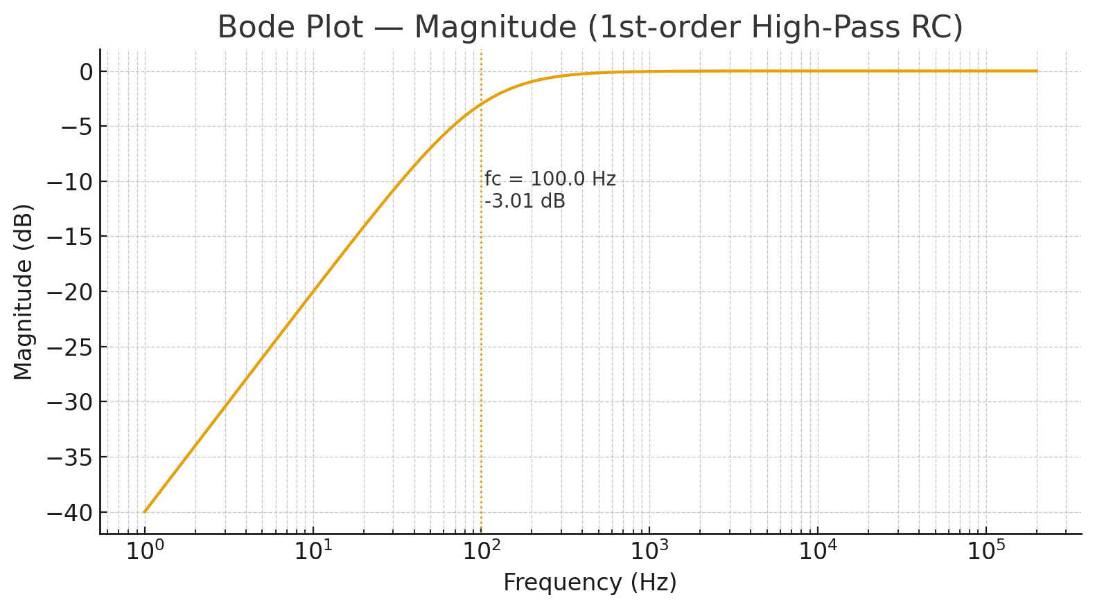
Magnitude Bode plot of a first-order RC high-pass filter designed for a 100 Hz cutoff frequency. The plot shows the −3 dB point at 100 Hz, where low-frequency components such as DC offset and rumble are effectively removed from the microphone signal.
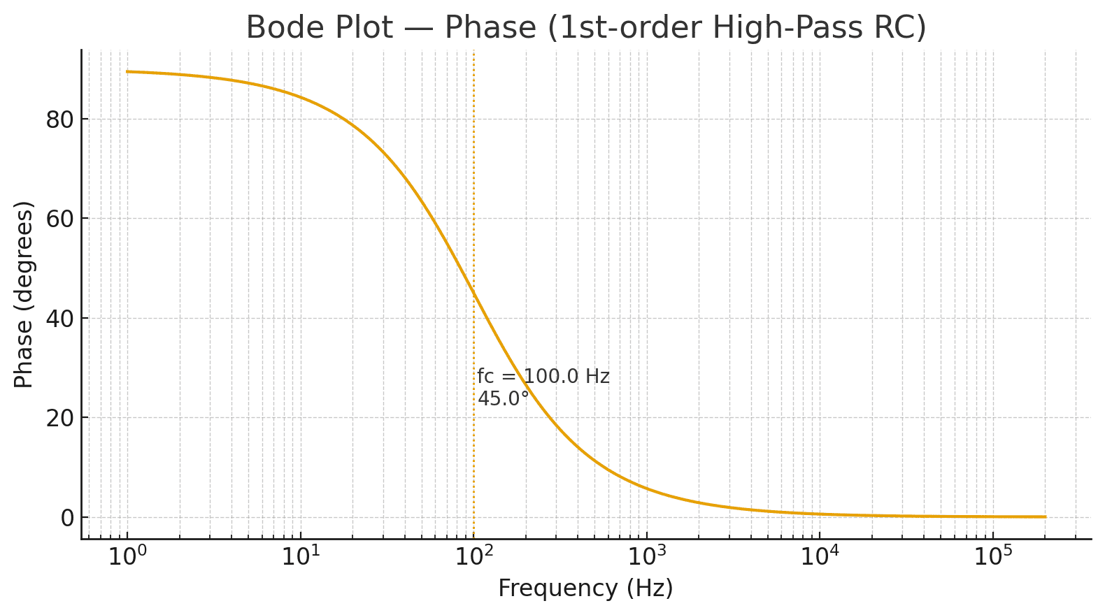
Phase response of the same RC high-pass filter. At the cutoff frequency (100 Hz), the output phase leads the input by approximately 45°, illustrating the filter’s characteristic frequency-dependent phase shift common in audio preamps.
Design Example 2: AC Coupling for Amplifier
Objective: Remove DC offset from amplifier input while preserving audio (20 Hz - 20 kHz)
- Desired cutoff frequency: 20 Hz (below audio range)
- Desired input impedance: 100 kΩ
- Select: R = 100 kΩ
Calculation:
Result: Use 82 nF (0.082 µF) capacitor At 20 Hz: -3dB (0.707 output) At 100 Hz: -0.3dB (0.96 output - minimal effect) At 20 kHz: essentially 0dB (full pass-through)
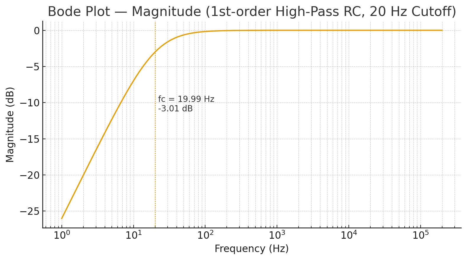
Magnitude Bode plot of a first-order RC high-pass filter designed for a 20 Hz cutoff frequency. The plot shows the −3 dB point near 20 Hz, indicating effective attenuation of very low-frequency components below the audible range.
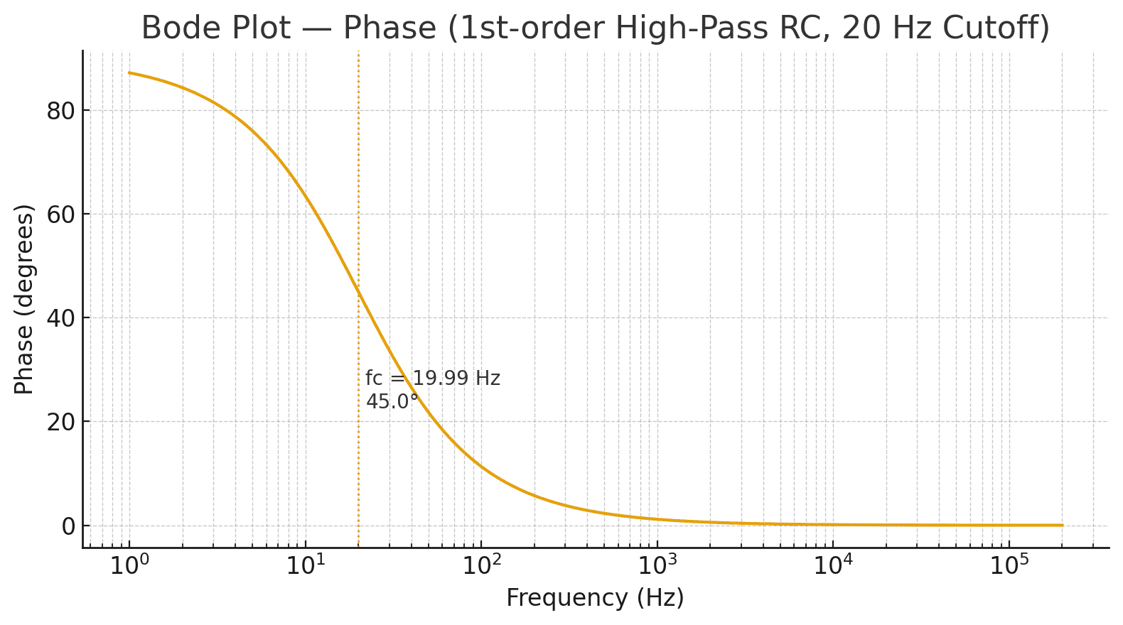
Phase response of the same RC high-pass filter. At the cutoff frequency (20 Hz), the output phase leads the input by approximately 45°, demonstrating the filter’s characteristic frequency-dependent phase shift in audio signal paths.
Frequency Response Characteristics
The frequency response of a first-order high pass filter has distinctive features:
Passband (frequencies well above fc):
- Attenuation: < 1dB
- Magnitude response: relatively flat
- Phase shift: approaching 0°
Transition Region (frequencies near fc):
- Attenuation: varies from 3dB to 20dB per decade
- Roll-off rate: 20 dB/decade (6 dB/octave)
- Phase shift: 0° to -90°
Stopband (frequencies well below fc):
- Attenuation: increases 20 dB for each frequency decade decrease
- At f = 0.1fc: approximately -20dB attenuation
- Phase shift: approaching -90°
High Pass Filter Design Calculations
Step-by-Step Design Process
Step 1: Define Requirements
- Determine required cutoff frequency
- Specify acceptable attenuation in passband
- Define desired input/output impedance
Step 2: Choose Component Values
- Select either R or C based on practical availability
- Standard values simplify procurement and design modifications
Step 3: Calculate Complementary Component
Use the formula: or
Step 4: Verify Performance
- Calculate actual cutoff frequency with real component values
- Verify output loading effects
- Check impedance compatibility
Complete Design Example: Instrumentation High Pass Filter
Problem: An accelerometer outputs signals from 0-500 Hz, but you need to remove DC and low-frequency drift below 1 Hz while preserving the 1-500 Hz signal content.
Requirements:
- Cutoff frequency: 1 Hz
- Input impedance: 1 MΩ (high impedance sensor)
- Passband attenuation: < 0.5 dB at 500 Hz
Design Process:
Step 1 - Choose Resistance: Select R = 1 MΩ (matches sensor impedance)
Step 2 - Calculate Capacitance:
Step 3 - Select Standard Value: Use C = 160 nF (0.16 µF) film capacitor
Step 4 - Verify Performance:
Actual ✓
At 500 Hz:
At 0.1 Hz (drift):
Solution: 1 MΩ resistor + 160 nF capacitor effectively removes drift while preserving sensor signal.
Decibel and Phase Response
Understanding attenuation in decibels is essential:
At Cutoff Frequency:
- Magnitude: 0.707
- Attenuation: 20 log₁₀(0.707) = -3.01 dB
One Octave Above Cutoff (f = 2fc):
- Magnitude: 1/√(1 + 0.25) = 0.894
- Attenuation: 20 log₁₀(0.894) = -0.97 dB
One Decade Above Cutoff (f = 10fc):
- Magnitude: 1/√(1 + 0.01) = 0.995
- Attenuation: 20 log₁₀(0.995) = -0.04 dB
One Decade Below Cutoff (f = 0.1fc):
- Magnitude: 1/√(1 + 100) = 0.0995
- Attenuation: 20 log₁₀(0.0995) = -20.04 dB
Practical Applications
1. Audio Signal Processing
AC Coupling in Microphone Preamplifiers
- Removes DC offset and very low-frequency components
- Typical cutoff frequency: 10-20 Hz
- Preserves speech and music (300 Hz - 3 kHz)
- Circuit: 100 nF capacitor with 10 kΩ input resistor
Rumble Filtering in Audio Equipment
- Removes low-frequency vibration and handling noise
- Typical cutoff frequency: 20-80 Hz
- Improves perceived audio quality
- Reduces power consumption in speaker systems
2. Biomedical Instrumentation
ECG (Electrocardiogram) Signal Conditioning
- Removes baseline wander (very low frequency drift)
- Cutoff frequency: 0.5-5 Hz
- Preserves diagnostic ECG frequencies (0.05-100 Hz)
- Critical for accurate heart rate and rhythm analysis
EEG (Electroencephalogram) Processing
- High pass filtering at 0.5-1 Hz removes DC and drift
- Low pass filtering at 70 Hz removes 50/60 Hz interference
- Enables reliable brain activity detection
3. Instrumentation and Measurement
Sensor Signal Conditioning
- Removes DC offset from sensor output
- Eliminates low-frequency noise and drift
- Protects analog-to-digital converter (ADC) dynamic range
- Example: Accelerometer high pass filter at 1-10 Hz
Vibration Analysis Equipment
- Removes low-frequency vibrations outside band of interest
- Typical frequencies: 10 Hz - 1 kHz
- Improves measurement signal-to-noise ratio
4. Power System Protection
High Voltage Power Quality Monitoring
- Removes 50/60 Hz fundamental and low-order harmonics
- Focuses on higher harmonic frequencies (>1 kHz)
- Detects arcing faults and transient events
- Improves protective relay coordination
High Pass Filter vs Low Pass Filter
Side-by-Side Comparison
| Parameter | High Pass Filter | Low Pass Filter |
|---|---|---|
| Frequency Response | Allows high frequencies, blocks low frequencies | Allows low frequencies, blocks high frequencies |
| Cutoff Frequency | Below cutoff: attenuated | Above cutoff: attenuated |
| Component Configuration | Series capacitor, shunt resistor | Series resistor, shunt capacitor |
| Applications | AC coupling, noise removal | Anti-aliasing, smoothing |
| Phase at Low f | -90° | 0° |
| Phase at High f | 0° | -90° |
| Roll-off | 20 dB/decade below fc | 20 dB/decade above fc |
Converting Between Filter Types
The relationship between high pass and low pass filters is straightforward: swap the resistor and capacitor positions.
High Pass Configuration:
Low Pass Configuration:
Both have the same cutoff frequency formula:
Choosing the Right Filter
Use High Pass Filter When:
- You need to remove DC offset or low-frequency drift
- AC coupling is required between circuit stages
- Signal of interest is at higher frequencies
- Removing baseline wander is critical
Use Low Pass Filter When:
- Anti-aliasing before analog-to-digital conversion
- Smoothing noisy signals
- Signal of interest is at lower frequencies
- Eliminating high-frequency noise and interference
Advanced Filter Design
Second-Order High Pass Filters
For steeper frequency response (40 dB/decade), cascade two first-order stages:
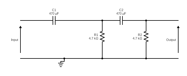
Characteristics:
- Roll-off rate: 40 dB/decade (12 dB/octave)
- Phase shift range: -180° to 0°
- Sharper cutoff than first-order filter
- Cutoff frequency depends on both RC stages
Multiple-Feedback High Pass Filter Configuration
For improved frequency response characteristics:
Configuration Benefits:
- Adjustable gain control
- Better frequency response shape
- Improved impedance buffering
- Useful for precision applications
Active High Pass Filters
Using operational amplifiers (op-amps) provides additional benefits:
Advantages:
- Adjustable gain without frequency distortion
- Low output impedance (easy to cascade)
- Less loading effects on input
- Precision cutoff frequency tuning
- Can implement complex transfer functions
Practical Circuit Construction Tips
PCB Layout Considerations
- Keep component leads short to minimize parasitic inductance
- Place capacitor close to resistor to maintain cutoff frequency accuracy
- Use ground plane for low-impedance return path
- Isolate high-impedance nodes from noise sources
- Consider shielding for very high-impedance circuits (> 10 MΩ)
Component Selection
Capacitor Types for Different Applications:
- Film capacitors: Best for frequency stability and audio applications
- Ceramic capacitors: Good for moderate impedance (< 100 kΩ), compact size
- Electrolytic capacitors: Not recommended for AC filtering due to poor frequency response
Resistor Considerations:
- Use 1% tolerance metal film resistors for accurate cutoff frequency
- Select values to minimize loading on both source and load impedances
- Consider temperature coefficient for stable frequency response
Conclusion: Mastering High Pass Filter Design
High pass filters remain one of the most essential tools in electronics and signal processing. Whether you’re designing a simple RC network or a multi-stage active filter, understanding how capacitive reactance changes with frequency is key to controlling which signals pass and which get attenuated.
These filters are used everywhere — from sensor signal conditioning and audio processing to motor control and communication circuits. The design process is simple yet powerful: choose your cutoff frequency, select accurate resistor and capacitor values, and verify your circuit’s response through analysis or simulation.
By mastering high pass filter design, you build a foundation that supports nearly every area of electrical and electronic engineering — from power systems to instrumentation and control.
Ready to strengthen your understanding of electrical fundamentals? Explore these detailed guides next:
🔗 Related Posts
- Exploring Electrical and Electronics Engineering Concepts
- Understanding Electrical Resistance: Complete Guide with Calculations and Real-World Examples
- Kirchhoff's Laws: Complete Guide with Circuit Analysis Examples & Calculations
- Understanding Electric Current: A Comprehensive Guide
- AC Capacitors Explained: Types, Applications & Complete Sizing Guide with Calculations
- Mastering PCB Design: Techniques, and Best Practices
Helpful Calculators
- Voltage Drop Calculator
- Ohm's Law Calculator
- Power Factor Calculator
- AC DC Current Calculator
- Capacitor and Inductor Reactance Calculator
Credits
- Photo by Random Thinking on Unsplash
⭐ Was this article helpful?
IDAR Mohamed
Electrical Engineer
Electrical Engineer specialized in power systems, electrical installations, and energy efficiency. Passionate about simplifying complex electrical concepts into practical guides. (University of applied sciences graduate, with experience in HV/LV systems and industrial installations.)
- High Pass Filter
- RC High Pass Filter
- Filter Circuit Design
- Frequency Response
- Cutoff Frequency