
Soft Starter Working Guide: How It Works, Sizing, Wiring & When to Use It
- Admin: IDAR Mohamed
- 30 May 2026
- 0
Walk through enough industrial facilities and you'll see the same sequence. A pump or conveyor motor starts direct-on-line, the lights dim, something sensitive on the same feeder glitches, and everyone moves on. Months later, the drivetrain shows wear that nobody connects back to the starting method. The cause is almost always inrush current from DOL starting.
Soft starters fix this. They are not complicated devices, but they need to be sized and configured correctly to do their job. This guide covers the electrical mechanics of motor starting, what a soft starter actually does about it, and the practical steps for sizing and wiring one correctly.
Table of Contents
- How an Induction Motor Actually Starts
- Calculating Inrush Current and Voltage Dip
- What Is a Soft Starter?
- Inside the Box: How It Works
- Sizing a Soft Starter — With Examples
- Ramp Time and Current Limit Calculations
- Soft Starter vs. Star-Delta vs. VFD
- Wiring Basics
- Application Notes and Common Mistakes
How an Induction Motor Actually Starts
When full voltage is applied to a stationary induction motor, the rotor is at standstill — electrically equivalent to a short-circuited transformer secondary. The stator winding sees nearly zero back-EMF, so it draws an enormous current to establish the rotating magnetic field.
This startup phase is defined by three simultaneous conditions:
- Inrush current: 5–7× full-load amperage (FLA), up to 9× for motors with high-inertia loads
- High slip: At standstill, slip = 1.0 — the rotor is stationary relative to the rotating magnetic field
- Low power factor: Typically 0.1–0.3 during the first cycles — the current is largely reactive
- Duration: 2–10 seconds to reach rated speed, depending on load inertia
The motor equivalent circuit at startup is dominated by the rotor resistance divided by slip. At slip = 1.0, rotor impedance collapses and line current surges. As the rotor accelerates and slip decreases, impedance rises and current normalises.
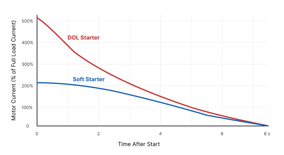
Figure: Inrush current profile during DOL starting vs. a controlled soft starter ramp.
Calculating Inrush Current and Voltage Dip
Understanding the numbers behind DOL starting makes the case for soft starters concrete.
Inrush Current — Example Calculation
Motor data:
- Rating: 37 kW, 400 V, three-phase, 50 Hz
- FLA (from nameplate): 70 A
- Starting current multiplier (Isc/In): 6.5× (typical for standard efficiency motors)
DOL inrush current:
This 455 A surge lasts 4–8 seconds until the rotor reaches rated speed. With a soft starter limiting current to 300% FLA:
That is a reduction of 245 A — less than half the DOL inrush — on the supply feeder.
Voltage Dip — Example Calculation
Voltage dip during motor starting depends on feeder impedance. For a simplified estimate:
Given:
- Feeder impedance to motor: 0.15 Ω (cable + transformer contribution)
- DOL inrush: 455 A
- Nominal voltage: 400 V (phase-to-phase) → 231 V per phase
A nearly 30% voltage dip on a shared busbar is severe — enough to drop contactors, trip drives, and cause PLC undervoltage faults on adjacent equipment. With a soft starter at 210 A:
Still noticeable, but within the tolerance of most industrial equipment (typically ±15%). On stiffer grids or with a higher current limit, the dip can be reduced further.
What Is a Soft Starter?
A soft starter is an electronic motor starting device that gradually increases the voltage applied to the motor from a configurable initial level up to full supply voltage over a set ramp time.
Core functions:
- Limit inrush current (typically 1.5–3.5× FLA during the ramp)
- Reduce mechanical shock on the drivetrain
- Provide soft stop (controlled voltage reduction during deceleration)
- Built-in motor protection: overload, phase loss/imbalance, thermistor input
Once the motor reaches full speed, most soft starters activate a bypass contactor — the motor then runs directly across the supply and the SCRs carry no current. A soft starter is a start and stop device only, not a running speed controller. This distinction matters for panel thermal design and energy efficiency.
Inside the Box: How It Works
The core of a soft starter is six back-to-back thyristors (SCRs) — two per phase. The SCR firing angle (α) determines what fraction of each AC half-cycle is conducted to the motor.
At α near 180°, almost no voltage passes. At α near 0°, the full half-cycle is conducted — full voltage. During startup, the controller progressively reduces α each cycle:
Example — voltage at 50% firing angle (α = 90°):
At α = 90°, the motor receives approximately 283 V — 70.7% of supply voltage. As the ramp progresses, α decreases toward zero and voltage climbs to the full 400 V.
Adjustable parameters on most soft starters:
| Parameter | Typical Range | Effect |
|---|---|---|
| Ramp time | 3–60 s | Longer = smoother acceleration, higher SCR thermal load |
| Current limit | 150–450% FLA | Lower limit = less grid impact; too low = stall risk |
| Initial voltage | 20–50% Vn | Starting torque pedestal — raise for loaded starts |
| Soft stop time | 0–60 s | Deceleration ramp — essential for pumps |
Sizing a Soft Starter — With Examples
The most common sizing error is using motor kW or HP as the selection parameter. Power output is mechanical — it does not directly represent the electrical current demand during starting.
Correct sizing steps:
- Read motor FLA from the nameplate
- Select soft starter with rated current ≥ motor FLA
- Check starts per hour against the soft starter's duty rating
- Select the duty class for the application:
- Pumps, fans: standard duty (motor accelerates in 5–10 s)
- Conveyors, mixers: medium duty
- Large fans, centrifuges, loaded belt conveyors: heavy duty (ramp time 15–30 s)
Example 1 — Centrifugal Pump
Motor: 45 kW, 400 V, three-phase | FLA: 88 A | Application: centrifugal pump, up to 10 starts/hour
Select a soft starter rated ≥ 88 A — a 90 A standard-duty model is appropriate. Current limit set to 300% FLA:
Ramp time of 5–8 seconds is sufficient for a centrifugal pump (low inertia load).
Example 2 — Large Exhaust Fan (High Inertia)
Motor: 75 kW, 400 V, three-phase | FLA: 140 A | Application: large exhaust fan, 4 starts/hour
The fan impeller has high rotational inertia — it takes 20–25 seconds to reach full speed. Even with the starter ramping voltage, the motor draws elevated current throughout this period.
Select a heavy-duty soft starter rated ≥ 140 A. In practice, stepping up to a 160 A or 175 A heavy-duty model gives thermal headroom:
Ramp time: 25 s. The larger model prevents SCR thermal shutdown during extended starting.
Example 3 — Loaded Conveyor Belt
Motor: 22 kW, 400 V | FLA: 44 A | Application: fully loaded belt conveyor
A loaded conveyor requires breakaway torque — low initial voltage will stall. Set initial voltage (pedestal) to 40% Vn:
At 160 V, available starting torque is approximately:
This is borderline for a loaded conveyor. Raise the pedestal to 50% Vn (200 V) for 25% of rated torque — usually sufficient to break the belt loose before the ramp continues.
Current limit: 350% FLA → 44 × 3.5 = 154 A. Ramp time: 8–12 s.
Ramp Time and Current Limit Calculations
Estimating Minimum Ramp Time from Motor Inertia
For loads where rotor inertia (GD² or WK²) is known, the approximate acceleration time can be estimated:
Where:
- = total moment of inertia (motor + load) in kg·m²
- = speed change (rpm) = rated speed
- = net accelerating torque (Nm) = average starting torque − load torque
- 375 = unit conversion constant
Example:
- GD² = 12 kg·m², rated speed = 1480 rpm
- Average net torque during start = 80 Nm
This is a low-inertia load — a 3–5 s ramp time is more than adequate. For a fan with GD² = 80 kg·m² and net torque of 60 Nm:
Add a 3–4× safety margin for the soft stop ramp and thermal reserve: set ramp time to 20–25 s for this fan.
Soft Stop Time for a Pump — Water Hammer Prevention
Water hammer occurs when a pump stops abruptly and the discharge column reverses. The critical parameter is the time constant of the hydraulic system. A soft stop ramp longer than this constant prevents column reversal.
A rule of thumb for centrifugal pumps:
Where:
- = pipe length (m)
- = flow velocity (m/s)
- = 9.81 m/s²
- = static head (m)
Example: L = 80 m, v = 2.5 m/s, = 30 m
In practice, set soft stop to 10–15 s minimum for pumping systems — the formula gives a physical lower bound, but longer ramps provide additional margin against pressure surge.
Soft Starter vs. Star-Delta vs. VFD
| DOL | Star-Delta | Soft Starter | VFD | |
|---|---|---|---|---|
| Inrush current | 5–7× FLA | ~2–3× FLA | 1.5–3.5× FLA | ≤1.5× FLA |
| Transition current spike | — | Yes (Y→Δ) | None | None |
| Torque control | None | Fixed | Adjustable | Full |
| Speed control during run | No | No | No | Yes |
| Built-in motor protection | No | No | Yes | Yes |
| Typical relative cost | Lowest | Low | Moderate | High |
Choose a soft starter when:
- Motor runs at fixed speed (centrifugal pump, fan, conveyor)
- Inrush current is causing supply disturbances or tripping adjacent equipment
- Mechanical shock during startup is damaging couplings or load machinery
- Starts per hour is moderate (fewer than 20)
- A VFD cannot be justified on cost grounds
Star-delta continues to appear in older panel designs and retrofit projects. The fundamental limitation is the open-transition spike at the Y-to-Δ changeover — a second current surge that can approach 4–5× FLA, partly negating the benefit of star connection. A soft starter eliminates this transition entirely. The star-delta starter wiring guide details the timing logic and tradeoffs.
Choose a VFD when:
- The process requires variable speed (flow control, speed-matched conveyors)
- Fan or pump affinity law savings justify the investment
- High-inertia loads require ramp times beyond 30 s with precise torque control
- Regenerative or dynamic braking is required
See the VFD complete guide for a full breakdown of VFD selection criteria.
Wiring Basics
A soft starter is wired in series between the main contactor and the motor. The standard bypass configuration:
Main power circuit:
- Supply → Main isolator → Main contactor → Soft starter inputs (R, S, T)
- Soft starter outputs (T1, T2, T3) → Motor terminals (U, V, W)
- Bypass contactor wired in parallel across the soft starter (line input shorted to motor output)
Control circuit:
- Start/stop command (PLC output, pushbutton, or SCADA) → Soft starter RUN input
- Soft starter "top-of-ramp" relay output → Bypass contactor coil (closes once motor reaches full speed)
- Soft starter fault relay → MCC alarm or PLC fault input
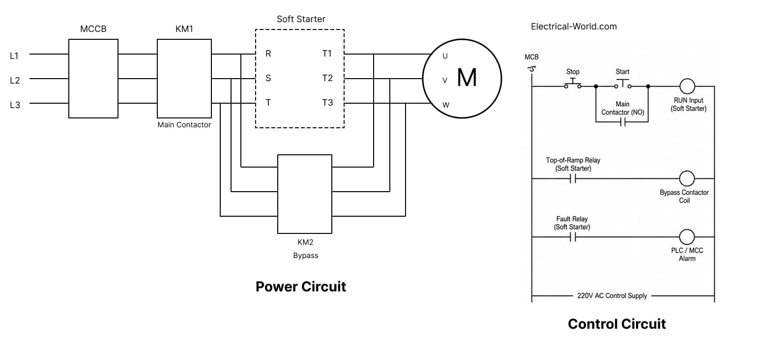
Figure: Three-phase soft starter wiring with main contactor, bypass contactor, and motor thermistor input.
Critical wiring rules:
- A main contactor upstream is mandatory for isolation — SCRs must not serve as the only disconnecting means
- Connect the motor PTC thermistor to the soft starter's thermistor terminals when available — this provides direct winding temperature protection without a separate relay
- Some units have an internal bypass relay; others require an external bypass contactor — confirm from the datasheet before panel layout
For overload relay coordination, see the motor overload protection guide. Verify motor cable sizing and voltage drop on long runs before commissioning.
Application Notes and Common Mistakes
Centrifugal pumps are the natural fit for soft starters. A controlled torque ramp eliminates water hammer on start, and a soft stop prevents pressure surge on valve closing. Both ramp-up and ramp-down times should be configured — defaulting to zero soft stop is a frequent oversight.
Conveyors with full loads need a torque pedestal (initial voltage set above minimum) to overcome static belt friction before the voltage ramp continues. Without it, the motor stalls at low voltage and current limit activates, causing excessive heat in the SCRs.
Centrifugal and screw compressors start unloaded in most designs, making them well-suited for soft starters. Reciprocating (piston) compressors require high breakaway torque — verify starting torque availability at the initial voltage setting before specifying a soft starter.
Large axial and centrifugal fans have high rotational inertia. Ramp time must match the mechanical acceleration time; setting it too short causes the starter to hit the current limit and extend the start automatically, increasing thermal stress on the SCRs.
Common mistakes that lead to failures:
- Sizing to kW instead of FLA — the nameplate amperage is the only correct basis
- No bypass contactor on continuous-duty installations — running load current continuously through SCRs causes thermal failure; bypass is not optional
- Ramp time set too short for high-inertia loads — the current limit extends the start but stresses the semiconductors; calculate ramp time from load inertia data before commissioning
- Bypass contactor closing too early — if bypass engages before the motor reaches full speed, the voltage step causes a current transient; use the starter's internal "at-speed" relay to control bypass timing
- Insufficient enclosure ventilation — soft starters dissipate approximately 3–4 W per ampere of motor current through the SCRs during starting; always verify thermal requirements from the manufacturer's documentation
🔗 Related Posts
- Understanding Induction Motors: Working Principle, Calculations, and Applications
- Star Delta Starter: Complete Wiring Guide with Timer Calculations & Troubleshooting
- Variable Frequency Drive (VFD): The Complete Guide to Working Principles, Types, and Applications
- Motor Overload Protection: Complete Sizing Guide with Charts & Selection Criteria
- Motor Voltage Drop Effects: Why Your Motors Fail and How to Fix It
- Motor Cable Size for 5 HP & 10 HP: Complete Selection Guide with Charts
- Contactor vs Relay: Complete Comparison Guide with Applications & Selection Criteria
- 3-Phase Power Calculation: Complete Guide with kW to Amps Formulas
Helpful Calculators
- Voltage Drop Calculator
- Ohm's Law Calculator
- Power Factor Calculator
- AC DC Current Calculator
- Capacitor and Inductor Reactance Calculator
- Resistor Color Code Calculator
- Transformer Ratio Calculator
- Series Parallel Resistance Calculator
Credits
- Photo by Raymond Sime on Unsplash
⭐ Was this article helpful?
IDAR Mohamed
Electrical Engineer
Electrical Engineer specialized in power systems, electrical installations, and energy efficiency. Passionate about simplifying complex electrical concepts into practical guides. (University of applied sciences graduate, with experience in HV/LV systems and industrial installations.)
- Motors and Drives
- Motor Control
- Star-Delta Connection
- Electrical Safety